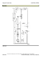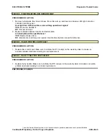
CAUSE B - CANBUS COMMUNICATION FAULT
PROCEDURE OR ACTION:
NOTE:
Perform Step 1 and Step 2 with key in ON position.
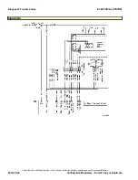
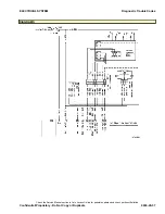
1. Measure voltage between connector CPS09 (PC Service Tool connector), socket C and socket A.
Is CAN HI voltage approximately 2.5 Vdc?
YES:
Proceed to Step 2.
NO:
Inspect CAN HI circuit for open or short. If voltage is 0 volts, the CAN HI circuit is shorted to ground or
open. If voltage is above 5 volts, the CAN HI circuit is shorted to power.
2. Measure voltage between connector CPS09, socket C and socket B.
Is CAN LO voltage approximately 2.5 Vdc?
YES:
Disconnect battery and proceed to Step 3.
NO:
Inspect CAN LO circuit for open or short. If voltage is 0 volts, the CAN LO circuit is shorted to ground or
open. If voltage is above 5 volts, the CAN LO circuit is shorted to power.
3. Measure voltage between connector CPS09, socket A and socket B.
Is resistance 60 ± 6 ohms?
YES:
No communication faults are present, connect battery and proceed to CAUSE C.
NO:
If resistance is 120 ohms, the CANbus has an open circuit or a missing or damaged termination resistor.
If resistance is 0 ohms, the CANbus circuits are shorted together.
CAUSE C - HANDLE WIRING FAULT
PROCEDURE OR ACTION:
NOTE:
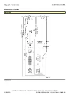
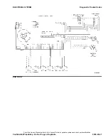
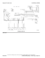
The CANbus has two 120 ohm termination resistors connected in parallel. One resistor is between the
tiller card and the traction controller. The second resistor is connected to the traction controller. With the tiller card
and traction controller disconnected from the harness, CANbus resistance is 120 ohms at the harness. Measuring
resistance between the traction controller connector CPS01, pins 21 and 34 will measure 120 ohms. When both
120 ohm resistors are correctly connected in parallel, a measurement of 60 ohms is expected.
NOTE:
Perform the following Step with key in ON position.
1. Disconnect connector CRP10 and measure voltage between pin 1 and pin 3.
Is voltage same as key switch voltage?
YES:
Disconnect the battery and proceed to Step 2.
NO:
Inspect circuit 010 for open or short.
2. Measure voltage between CPS01, pin 9 and B(-). Move tiller arm within operational region, ensure interlock
LED is illuminated.
Is voltage same as key switch voltage?
YES:
Proceed to CAUSE F.
NO:
Proceed to Step 3.
3. Disconnect traction controller connector CPS01, tiller harness connector CRP06, and interlock sensor
CRP10. Measure resistance between CRP06/pin 6, CRP10/pin 2, CPS01/socket 9.
Is resistance ≤ 1 ohm?
YES:
Proceed to CAUSE D.
NO:
Inspect circuit 601 for open, shorts or source of excessive resistance.
Diagnostic Trouble Codes
ELECTRICAL SYSTEM
Check the Service Manual section in Yale Axcess Online for possible updates and check pertinent Bulletins
9030-20-44
Confidential/Proprietary - Do Not Copy or Duplicate
Summary of Contents for MPB045VG
Page 1: ...Maintenance CONTROLLER DIAGNOSTICS MPB045VG A245 PART NO 550095689 9000 YRM 1671 ...
Page 4: ......
Page 6: ......
Page 10: ...9030 4 ...
Page 24: ...NOTES 9030 03 14 ...
Page 83: ......
Page 84: ...9000 YRM 1671 10 19 9 15 1 15 12 14 10 14 4 14 ...

