background image

Status Codes and Descriptions

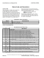
STATUS CODES

Status codes give an indication to the operator that a
possible malfunction or incorrect truck use has
occurred. Status codes are a code number of a
symptom or malfunction. The wrench symbol will flash
and the status code number will be shown on the LCD
screen if an incorrect truck use or malfunction occurs
during operation. Have an authorized service person
check and repair the lift truck if a status code number
appears. The symptoms for each status code are

shown in this manual. This manual also provides in-
depth troubleshooting procedures for each fault broken
down into the following system or node:

NODE 30:

 TRACTION CONTROLLER

NODE 60:

 TILLER CARD

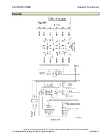
Status Codes are displayed as four lines. Line one
consist of the Node and Code number. The second
line consists of the Node name while lines three and
four contain code descriptions.

Table 9030-03-1. Status Code Example

DISPLAY

LINE DESCRIPTION

First Display String

Diagnostic Trouble Code

Subsequent Display String

Code Description/Affected Circuit

STATUS CODE DESCRIPTIONS

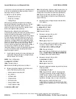
Table 9030-03-2. Node 30 Status Codes

NODE

STATUS

DESCRIPTION

XX

099

Internal Fault*

30

001

The Traction Controller has detected a fault in the Lift Coil circuit.

30

003

The Traction Controller has detected a fault in the Lower Coil circuit.

30

033

The Traction Controller has detected a fault in the Main Contactor Coil circuit.

30

035

The Traction Controller had detected a fault in the Brake Coil circuit.

30

037

The Traction Controller has detected a fault in the Audible Alarm circuit.

30

039

The Traction Controller has detected a fault in the Optional Audible Alarm circuit.

30

052

The Traction Controller has detected a fault in the Beverage Handle Option, Thumb Lift/
Lower Switch circuit.

30

060

The Traction Controller has detected high current in the traction motor or traction motor cir-
cuit.

30

061

The Traction Controller has detected a open/short in the Traction Motor or circuit.

30

062

The Traction Controller has detected a motor encoder fault.

30

067

The Traction Controller has detected that the Main Contactor is stuck closed or has welded
tips.

30

068

The Traction Controller has detected that the Main Contactor is not closed or stuck open.

30

069

The Traction Controller has detected a fault in Capacitor charge.

30

080

The Traction Controller has detected the motor operating at high temperatures/Cutback
Mode.

30

082

The Traction Controller is operating at high temperatures/Cutback Mode.

General Maintenance and Diagnostic Data

ELECTRICAL SYSTEM

Check the Service Manual section in Yale Axcess Online for possible updates and check pertinent Bulletins

9030-03-12

Confidential/Proprietary - Do Not Copy or Duplicate

Summary of Contents for MPB045VG

Page 1: ...Maintenance CONTROLLER DIAGNOSTICS MPB045VG A245 PART NO 550095689 9000 YRM 1671 ...

Page 2: ...K ON BLOCKS in the Operating Manual or the Periodic Maintenance section Keep the unit clean and the working area clean and orderly Use the correct tools for the job Keep the tools clean and in good condition Always use YALE APPROVED parts when making repairs Replacement parts must meet or exceed the specifications of the original equipment manufacturer Make sure all nuts bolts snap rings and other...

Page 3: ...OF CONTENTS SECTION 9030 ELECTRICAL SYSTEM Group 03 General Maintenance and Diagnostic Data 9030 03 1 Group 20 Diagnostic Trouble Codes 9030 20 1 This section is for the following models MPB045VG A245 CONTROLLER DIAGNOSTICS Table of Contents i ...

Page 4: ......

Page 5: ...a The General Maintenance and Diagnostic Data group includes general troubleshooting discharging the capacitors basic electrical troubleshooting multiplexing User Iterface and status codes and descriptions 20 Diagnostic Trouble Codes The Diagnostic Trouble Codes group includes all troubleshooting procedures for status codes reported by a given Node or system For a listing of all Diagnostic Trouble...

Page 6: ......

Page 7: ... Setup and Troubleshooting 9030 03 7 Status Code Indication 9030 03 7 Parameters 9030 03 7 Speed Steering Reduction 9030 03 8 Traction Steering Decel Ramp 9030 03 8 Response Full Accel Rate HS 9030 03 8 Response Full Accel Rate LS 9030 03 8 Response Low Accel Rate 9030 03 8 Response Neutral Decel Rate HS 9030 03 8 Response Neutral Decel Rate LS 9030 03 8 Fine Tuning Partial Decel Rate 9030 03 8 Fi...

Page 8: ...enance 9030 03 11 Status Codes and Descriptions 9030 03 12 Status Codes 9030 03 12 Status Code Descriptions 9030 03 12 Group 20 Diagnostic Trouble Codes DTC XX099 Internal Fault 9030 20 1 DTC 30001 LiftCoil 9030 20 2 DTC 30003 LwrCoil 9030 20 4 DTC 30033 Main Cont 9030 20 6 DTC 30035 Brake 9030 20 9 DTC 30037 AlrmCoil 9030 20 13 DTC 30039 Audible Alarm Opt 9030 20 15 DTC 30060 Mtr Curr 9030 20 17 ...

Page 9: ...TC 30248 Low Temp 9030 20 53 DTC 60050 EmerRevr 9030 20 55 DTC 60210 EmerRevr 9030 20 55 Check the Service Manual section in Yale Axcess Online for possible updates and check pertinent Bulletins Confidential Proprietary Do Not Copy or Duplicate 9030 3 ...

Page 10: ...9030 4 ...

Page 11: ...oted by the onboard diagnostic system The controllers are sealed units with no serviceable components Troubleshooting is usually limited to accessing status codes and following the diagnostic procedure provided for each status code Use standard testing procedures to verify inputs and outputs when necessary CAUTION Never attempt to probe through the back of the connector plugs of the motor controll...

Page 12: ...electrical compartments Make certain that the battery has been disconnected DO NOT short across the motor controller termi nals with a screwdriver or jumper wire CAUTION To avoid controller damage always disconnect the battery discharge the internal or external capaci tors and never put power to the controller while any power wires are disconnected Never short any controller terminal or motor term...

Page 13: ...erates correctly with the jumper wire in place and is faulty when the jumper wire is removed a fault can be found in the bypassed location Jumper wires can also be used to eliminate sections of the circuit to diagnose either power or grounds Using the jumper wire to provide a component a known good ground can help reduce the amount of checks needed to diagnose a circuit Jumper wires can be used to...

Page 14: ...tivie wire after FU1 B and B U Phase cable V Phase cable W Phase cable Pump positive cable Pump negative cable Is resistance 1M ohm YES Charge battery perform battery maintenance for non maintenance free batteries read battery Specific Gravity level to be within manufacturer specification NO Inspect for all cable insualtion throughout the truck Inspect battery corrosion around terminals for proper...

Page 15: ...l s positive terminal and B NOTE Key in ON position Is voltage same as truck s battery voltage YES Proceed to Step 2 NO Inspect the Coil s battery B input circuit for open or short 2 Disconnect coil s ground control circuit Measure resistance between ground circuit terminal and B NOTE Actuate coil ground control to determine if controller is sending activation signal to coil Is resistance 1 ohm YE...

Page 16: ...High On and Low Off This eliminates the need for each module to be hard wired to each sensor Using Multiplexing sensor information that may be received by one module can then be shared with all other modules The information is sent out over the CANbus in an encoded form and any other module that requires the information can pick it out from the data stream The CANbus has two termination resistors ...

Page 17: ...rams to detect and correct open circuit Troubleshooting the Tiller Control Card Termination Resistor Disconnect all Tiller Control Card connectors and components 1 Measure resistance between the Tiller Control Card connector CJ2 pin 1 and pin 2 Is resistance 120 12 ohms YES Reconnect the Tiller Control Card connectors components and proceed to Troubleshooting the Traction Controller Termination Re...

Page 18: ...conds at which the speed command increases when full throttle is applied at low vehicle speeds Response Low Accel Rate This parameter sets the rate in seconds at which the speed command increases when a small amount of throttle is applied This rate is typically adjusted to affect low speed maneuverability Response Neutral Decel Rate HS This parameter sets the rate in seconds that is used to slow d...

Page 19: ...This parameter sets the rate in seconds at which the motor speed command increases when throttle is applied when truck is not in turtle mode Larger values represent slower response Mode 1 through 3 Max Decel This parameter sets the rate in seconds that is used to slow down the vehicle when the throttle is reduced Larger values represent slower response Mode 1 through 3 Neutral Braking This paramet...

Page 20: ...BDI Reset Volts The reset voltage level is checked only once when KSI is first turned on Note that the BDI Reset Percent parameter also influences the algorithm that determines whether BDI Percentage is reset to 100 Reset Volts Per Cell should always be set higher than Full Volts Per Cell Battery BDI Full Volts The full voltage level sets the Keyswitch Voltage that is considered to be state of cha...

Page 21: ...voltage threshold can never be lowered below the controller s power base minimum voltage rating Total Maintenance Enable This parameter will activate BDI maintenance reminder for truck to be serviced after certain amount of total hours have been accumulated in the hour meters Traction Maintenance Enable This parameter will activate BDI maintenance reminder for truck to be serviced after certain am...

Page 22: ...ion Controller has detected a fault in the Lower Coil circuit 30 033 The Traction Controller has detected a fault in the Main Contactor Coil circuit 30 035 The Traction Controller had detected a fault in the Brake Coil circuit 30 037 The Traction Controller has detected a fault in the Audible Alarm circuit 30 039 The Traction Controller has detected a fault in the Optional Audible Alarm circuit 30...

Page 23: ...etected software update request 30 247 The Traction Controller has detected parameter update request 30 248 The Traction Controller has detected temperatures below controller operating range The Traction Controller and Tiller Control Card can detect an internal fault and is capable of reporting a 099 Status Code Refer to the XX099 Status Code troubleshooting procedures for all Internal Fault Codes...

Page 24: ...NOTES 9030 03 14 ...

Page 25: ...to Step 2 2 Re key the vehicle Is the code still present YES Proceed to CAUSE A NO Problem may be intermittent CAUSE A INTERNAL FAULT PROCEDURE OR ACTION 1 Replace faulty controller or tiller card Make sure to indicate the Diagnostic Trouble Code on the warranty claim to include an accurate problem description leading to controller replacement END POSSIBLE CAUSES END FAULT ELECTRICAL SYSTEM Diagno...

Page 26: ... coil terminal TS11 and B Is voltage 24 2 5 Vdc YES Disconnect battery and proceed to Step 2 NO Inspect circuit 239 for open or short 2 Disconnect connector CPS01 and measure resistance between socket 4 and the pump coil terminal TS11 Is resistance 1 ohm YES Connect CPS01 connect battery and proceed to Step 3 NO Inspect circuit 028 for open short or source of excessive resistance 3 Measure voltage...

Page 27: ...im to include an accurate problem description leading to controller replacement END POSSIBLE CAUSES DIAGRAMS Lift Coil and Pump Contactor END FAULT ELECTRICAL SYSTEM Diagnostic Trouble Codes Check the Service Manual section in Yale Axcess Online for possible updates and check pertinent Bulletins Confidential Proprietary Do Not Copy or Duplicate 9030 20 3 ...

Page 28: ...nector CRS05 socket 1 and B Is voltage 24 2 5 Vdc YES Disconnect battery and proceed to Step 2 NO Inspect circuit 239 for open or short 2 Disconnect lower coil connector CPS01 and measure continuity between CRS05 socket 2 and CPS 01 socket 3 Is resistance 1 ohm YES Connect CPS01 connect battery and proceed to Step 3 NO Inspect circuit 801 for open short or source of excessive resistance 3 Measure ...

Page 29: ...laim to include an accurate problem description leading to controller replacement END POSSIBLE CAUSES DIAGRAMS Lower Coil and Pump Motor END FAULT ELECTRICAL SYSTEM Diagnostic Trouble Codes Check the Service Manual section in Yale Axcess Online for possible updates and check pertinent Bulletins Confidential Proprietary Do Not Copy or Duplicate 9030 20 5 ...

Page 30: ...RE OR ACTION NOTE Key in ON position 1 Disconnect the main contactor coil s positive socket terminal TS007 and measure voltage between socket terminal TS007 and B Is voltage 24 2 5 Vdc YES Proceed to Step 2 NO Inspect circuit W239 B for open or short NOTE Key in OFF position 2 Disconnect traction controller connector CPS001 and the contactor coil s negative socket terminal TS008 Measure resistance...

Page 31: ...TRACTION CONTROLLER PROCEDURE OR ACTION 1 If no faults are found replace controller Make sure to indicate the DTC code s on the warranty claim to include an accurate problem description leading to controller replacement END POSSIBLE CAUSES ELECTRICAL SYSTEM Diagnostic Trouble Codes Check the Service Manual section in Yale Axcess Online for possible updates and check pertinent Bulletins Confidentia...

Page 32: ...tor and Contactor Coil END FAULT Diagnostic Trouble Codes ELECTRICAL SYSTEM Check the Service Manual section in Yale Axcess Online for possible updates and check pertinent Bulletins 9030 20 8 Confidential Proprietary Do Not Copy or Duplicate ...

Page 33: ...et 1 and B Note voltage reading reconnect CPS01 cycle key switch Disconnect brake coil connector CRP04 A and measure voltage between CRP04 A socket 1 and B Is voltage same as key switch input YES Disconnect battery and proceed to CAUSE B NO Inspect circuit 239 for open or short CAUSE B BRAKE COIL FAULT PROCEDURE OR ACTION 1 Measure resistance between CPS01 socket 5 and CRP04 A socket 1 Is resistan...

Page 34: ...AUSES Diagnostic Trouble Codes ELECTRICAL SYSTEM Check the Service Manual section in Yale Axcess Online for possible updates and check pertinent Bulletins 9030 20 10 Confidential Proprietary Do Not Copy or Duplicate ...

Page 35: ... Coil ELECTRICAL SYSTEM Diagnostic Trouble Codes Check the Service Manual section in Yale Axcess Online for possible updates and check pertinent Bulletins Confidential Proprietary Do Not Copy or Duplicate 9030 20 11 ...

Page 36: ... Diagnostic Trouble Codes ELECTRICAL SYSTEM Check the Service Manual section in Yale Axcess Online for possible updates and check pertinent Bulletins 9030 20 12 Confidential Proprietary Do Not Copy or Duplicate ...

Page 37: ...alarm connector TS09 and measure voltage between socket 1 and B Is voltage 24 2 5 Vdc YES Disconnect battery and proceed to Step 2 NO Inspect circuit 239 for open or short 2 Disconnect the traction connector CPS01 Measure resistance between the traction connector CPS01 socket 20 and the alarm connector TS09 Is resistance 1 ohm YES Connect traction controller connector CPS01 and proceed to CAUSE B ...

Page 38: ...ranty claim to include an accurate problem description leading to controller replacement END POSSIBLE CAUSES DIAGRAMS Horn Alarm END FAULT Diagnostic Trouble Codes ELECTRICAL SYSTEM Check the Service Manual section in Yale Axcess Online for possible updates and check pertinent Bulletins 9030 20 14 Confidential Proprietary Do Not Copy or Duplicate ...

Page 39: ...ure voltage between socket 1 and B Is voltage 24 2 5 Vdc YES Disconnect battery and proceed to Step 2 NO Inspect circuit 010 for open or short 2 Disconnect the traction connector CPS01 Measure resistance between the traction connector CPS01 socket 2 and the alarm connector CPS13 socket 2 Is resistance 1 ohm YES Connect traction controller connector CPS01 and proceed to CAUSE B NO Inspect ground co...

Page 40: ...e warranty claim to include an accurate problem description leading to controller replacement END POSSIBLE CAUSES DIAGRAMS END FAULT Diagnostic Trouble Codes ELECTRICAL SYSTEM Check the Service Manual section in Yale Axcess Online for possible updates and check pertinent Bulletins 9030 20 16 Confidential Proprietary Do Not Copy or Duplicate ...

Page 41: ...ll present YES Proceed to CAUSE A NO Problem may be intermittent CAUSE A TRACTION MOTOR CABLE FAULT PROCEDURE OR ACTION 1 Inspect controller phase cable terminals for proper torque and connections Are phase cables properly secured YES Proceed to Step 2 NO Repair and properly torque cables 2 Disconnect the traction motor cables from the traction controller and traction motor Measure continuity of i...

Page 42: ...terminals W and V Is continuity present YES Proceed to CAUSE C NO Repair or replace faulty traction motor CAUSE C FAULTY TRACTION CONTROLLER PROCEDURE OR ACTION 1 If no faults are found replace controller Make sure to indicate the DTC code s on the warranty claim to include an accurate problem description leading to controller replacement END POSSIBLE CAUSES DIAGRAMS Traction Motor END FAULT Diagn...

Page 43: ...n or short 2 Measure voltage between the encoder connector CPS03 socket 1 and socket 4 Is voltage 5 0 5 Vdc YES Disconnect battery and proceed to Step 3 NO Inspect ground circuit 102 for open or short 3 Disconnect the Combination controller connector CPS01 Measure resistance between socket 32 of the Combination controller connector and socket 3 of the encoder connector CPS03 Is resistance 1 ohm YE...

Page 44: ...YES Proceed to CAUSE C NO Replace faulty encoder CAUSE C FAULTY TRACTION CONTROLLER PROCEDURE OR ACTION 1 If no faults are found replace controller Make sure to indicate the DTC code s on the warranty claim to include an accurate problem description leading to controller replacement END POSSIBLE CAUSES DIAGRAMS Traction Motor END FAULT Diagnostic Trouble Codes ELECTRICAL SYSTEM Check the Service M...

Page 45: ... coil s positive socket terminal TS07 and measure voltage between the terminal and B Is voltage 24 2 5 Vdc YES Disconnect battery and proceed to Step 2 NO Inspect circuit 239 for open or short 2 Disconnect the traction controller connector CPS01 and the contactor coil negative terminal TS08 Measure continuity between TS08 and socket 6 of the traction controller CPS01 Is continuity present YES Reco...

Page 46: ...de s on the warranty claim to include an accurate problem description leading to controller replacement END POSSIBLE CAUSES Diagnostic Trouble Codes ELECTRICAL SYSTEM Check the Service Manual section in Yale Axcess Online for possible updates and check pertinent Bulletins 9030 20 22 Confidential Proprietary Do Not Copy or Duplicate ...

Page 47: ... ELECTRICAL SYSTEM Diagnostic Trouble Codes Check the Service Manual section in Yale Axcess Online for possible updates and check pertinent Bulletins Confidential Proprietary Do Not Copy or Duplicate 9030 20 23 ...

Page 48: ...ND FAULT Diagnostic Trouble Codes ELECTRICAL SYSTEM Check the Service Manual section in Yale Axcess Online for possible updates and check pertinent Bulletins 9030 20 24 Confidential Proprietary Do Not Copy or Duplicate ...

Page 49: ...t terminal TS07 and measure voltage between the terminal and B Is voltage 24 2 5 Vdc YES Disconnect battery and proceed to Step 2 NO Inspect circuit 239 for open or short 2 Disconnect the traction controller connector CPS01 and the contactor coil negative terminal TS08 Measure continuity between TS08 and socket 6 of the traction controller CPS01 Is continuity present YES Reconnect battery and all ...

Page 50: ...lty main contactor CAUSE D FAULTY TRACTION CONTROLLER PROCEDURE OR ACTION 1 If no faults are found replace controller Make sure to indicate the DTC code s on the warranty claim to include an accurate problem description leading to controller replacement END POSSIBLE CAUSES Diagnostic Trouble Codes ELECTRICAL SYSTEM Check the Service Manual section in Yale Axcess Online for possible updates and che...

Page 51: ... ELECTRICAL SYSTEM Diagnostic Trouble Codes Check the Service Manual section in Yale Axcess Online for possible updates and check pertinent Bulletins Confidential Proprietary Do Not Copy or Duplicate 9030 20 27 ...

Page 52: ...ND FAULT Diagnostic Trouble Codes ELECTRICAL SYSTEM Check the Service Manual section in Yale Axcess Online for possible updates and check pertinent Bulletins 9030 20 28 Confidential Proprietary Do Not Copy or Duplicate ...

Page 53: ...PC Service Tool enable main contactor and view diagnostics for capacitor voltage and battery voltage Is CAP voltage same as battery voltage YES Verify battery state of charge and recheck condition If actual voltage does not agree with PC service tool diagnostics proceed to CAUSE B NO Proceed to CAUSE A CAUSE A CONTROLLER WIRING FAULT PROCEDURE OR ACTION 1 Measure voltage between the traction contr...

Page 54: ...FAULT Diagnostic Trouble Codes ELECTRICAL SYSTEM Check the Service Manual section in Yale Axcess Online for possible updates and check pertinent Bulletins 9030 20 30 Confidential Proprietary Do Not Copy or Duplicate ...

Page 55: ...ght load and rated capacities CAUSE A WIRING FAULT PROCEDURE OR ACTION 1 Perform Voltage Checks as indicated in the Basic Electrical Troubleshooting section Did code clear YES Clear error log and verify correct operation NO Disconnect battery and proceed to Step 2 2 Disconnect CPS01 and CPS02 Measure resistance between CPS01 socket 8 and CPS02 socket 1 Is resistance 1 ohm YES Connect CPS01 and pro...

Page 56: ...action Motor END FAULT Diagnostic Trouble Codes ELECTRICAL SYSTEM Check the Service Manual section in Yale Axcess Online for possible updates and check pertinent Bulletins 9030 20 32 Confidential Proprietary Do Not Copy or Duplicate ...

Page 57: ...E A LOW BATTERY CONDITION PROCEDURE OR ACTION 1 Measure voltage between B at the controller and FU1 above controller Is voltage 25 0 5 Vdc YES Proceed to CAUSE B NO Charge battery CAUSE B CONTROLLER WIRING FAULT PROCEDURE OR ACTION NOTE Key in OFF position 1 Measure voltage between the traction controller B terminal and B Is precharge voltage same as battery voltage YES Proceed to CAUSE C NO Inspe...

Page 58: ...GRAMS END FAULT Diagnostic Trouble Codes ELECTRICAL SYSTEM Check the Service Manual section in Yale Axcess Online for possible updates and check pertinent Bulletins 9030 20 34 Confidential Proprietary Do Not Copy or Duplicate ...

Page 59: ...ER TERMINALS PROCEDURE OR ACTION 1 Measure voltage between B at the controller and FU1 above controller Is voltage above 26 Vdc YES Ensure battery is rated at 24V and is properly connected to the truck NO Proceed to CAUSE B CAUSE B CONTROLLER WIRING FAULT PROCEDURE OR ACTION NOTE Key in OFF position 1 Measure voltage between the traction controller B terminal and B Is precharge voltage same as bat...

Page 60: ...GRAMS END FAULT Diagnostic Trouble Codes ELECTRICAL SYSTEM Check the Service Manual section in Yale Axcess Online for possible updates and check pertinent Bulletins 9030 20 36 Confidential Proprietary Do Not Copy or Duplicate ...

Page 61: ...epair replace connector or wiring associated with faults found Refer to the appropriate Electrical SystemYRM NO Proceed to Step 2 2 Re key the vehicle Is the code still present YES Proceed to Step 3 NO Problem may be intermittent 3 Using the PC Service Tool locate input diagnostics Is thumb switch activation detected YES Fault may be intermittent NO Proceed to CAUSE A ELECTRICAL SYSTEM Diagnostic ...

Page 62: ...der CPS03 and battery display CRS07 Measure resistance between CPS03 socket 1 and CPS01 socket 26 is resistance 1 ohm YES Proceed to CAUSE D NO Inspect circuit 250 for open short or source of excessive resistance CAUSE B BATTERY DISPLAY FAULT PROCEDURE OR ACTION 1 If faults are found when reconnecting replace BDI Make sure to indicate the DTC code s on the warranty claim to include an accurate pro...

Page 63: ...GRAMS END FAULT ELECTRICAL SYSTEM Diagnostic Trouble Codes Check the Service Manual section in Yale Axcess Online for possible updates and check pertinent Bulletins Confidential Proprietary Do Not Copy or Duplicate 9030 20 39 ...

Page 64: ...propriate Electrical SystemYRM NO Proceed to Step 2 2 Re key the vehicle Is the code still present YES Proceed to Step 3 NO Problem may be intermittent 3 Perform multiplexing checks see the Multiplexing Section Are any CANbus circuit faults present YES Repair and retest system NO Proceed to Step 4 4 Measure resistance between frame and CANbus circuits Is resistance 1M ohm YES Proceed to CAUSE A NO...

Page 65: ...amaged termination resistor If resistance is 0 ohms the CANbus circuits are shorted together CAUSE B TILLER CARD WIRING FAULT PROCEDURE OR ACTION NOTE Perform Steps 1 through 4 with key in ON position 1 Open control handle observe tiller card assembly Is CRS03 connected to Tiller Card JP1 YES Proceed to Step 2 NO Connect tiller harness to JP1 2 With control handle open observe tiller card LCD disp...

Page 66: ...o include an accurate problem description leading to controller replacement END POSSIBLE CAUSES DIAGRAMS Control Card END FAULT Diagnostic Trouble Codes ELECTRICAL SYSTEM Check the Service Manual section in Yale Axcess Online for possible updates and check pertinent Bulletins 9030 20 42 Confidential Proprietary Do Not Copy or Duplicate ...

Page 67: ...propriate Electrical SystemYRM NO Proceed to Step 2 2 Re key the vehicle Is the code still present YES Proceed to CAUSE B NO Problem may be intermittent CAUSE A INCORRECT START UP SEQUENCE PROCEDURE OR ACTION 1 The fault code may occur when the operator commands traction when traction interlock sensor is OFF or if driving tiller arm traveled outside of tiller arm operational range Refer to Electri...

Page 68: ...n parallel One resistor is between the tiller card and the traction controller The second resistor is connected to the traction controller With the tiller card and traction controller disconnected from the harness CANbus resistance is 120 ohms at the harness Measuring resistance between the traction controller connector CPS01 pins 21 and 34 will measure 120 ohms When both 120 ohm resistors are cor...

Page 69: ...manual for reference CAUSE E TILLER CONTROL CARD FAULT PROCEDURE OR ACTION 1 Replace tiller control card Make sure to indicate the DTC code s on the warranty claim to include an accurate problem description leading to card replacement CAUSE F FAULTY TRACTION CONTROLLER PROCEDURE OR ACTION 1 Replace faulty handle Make sure to indicate the DTC code s on the warranty claim to include an accurate prob...

Page 70: ... Diagnostic Trouble Codes ELECTRICAL SYSTEM Check the Service Manual section in Yale Axcess Online for possible updates and check pertinent Bulletins 9030 20 46 Confidential Proprietary Do Not Copy or Duplicate ...

Page 71: ... ELECTRICAL SYSTEM Diagnostic Trouble Codes Check the Service Manual section in Yale Axcess Online for possible updates and check pertinent Bulletins Confidential Proprietary Do Not Copy or Duplicate 9030 20 47 ...

Page 72: ...raction motor Disconnect CRP04 B and CRP04 A connect CRP04 B to the electromagnetic brake connector Move the truck back and forward and move handle side to side Does truck move and rotate freely YES Connect CRP04 B AND CRP04 A and proceed to Step 3 NO Inspect transmission 3 Conduct a visual inspection of all connectors wiring associated with the fault code Are any faults detected observed YES Repa...

Page 73: ...circuit 577 for open or source of excessive resistance CAUSE B FAULTY TRACTION ENCODER PROCEDURE OR ACTION 1 Measure voltage between sockets 31 32 and B of the traction connector CPS01 operate traction motor Was voltage present YES Proceed to CAUSE D NO Replace encoder Make sure to indicate the DTC code s on the warranty claim to include an accurate problem description leading to controller replac...

Page 74: ...nty claim to include an accurate problem description leading to controller replacement END POSSIBLE CAUSES DIAGRAMS Traction Motor END FAULT Diagnostic Trouble Codes ELECTRICAL SYSTEM Check the Service Manual section in Yale Axcess Online for possible updates and check pertinent Bulletins 9030 20 50 Confidential Proprietary Do Not Copy or Duplicate ...

Page 75: ...ool and observe Truck Report Connect to FST download software and CDF file Once download is complete rekey the truck Is the code still present YES Clear error fault code from history Make sure to indicate the DTC code s on the warranty claim to include an accurate problem description of service provided NO Proceed to CAUSE B CAUSE B FAULTY TRACTION CONTROLLER PROCEDURE OR ACTION 1 If no faults are...

Page 76: ...Tool and observe Truck Report Connect to FST download software and CDF file Once download is complete rekey the truck Is the code still present YES Clear error fault code from history Make sure to indicate the DTC code s on the warranty claim to include an accurate problem description of service provided NO Proceed to CAUSE B CAUSE B FAULTY TRACTION CONTROLLER PROCEDURE OR ACTION 1 If no faults ar...

Page 77: ...oting section Is the code still present YES Clear error log Make sure to indicate the DTC code s on the warranty claim to include an accurate problem description of service provided NO Proceed to Step 2 2 Disconnect CPS01 and CPS02 Measure resistance between CPS01 socket 8 and CPS02 socket 1 Is resistance 1 ohm YES Connect CPS01 and proceed to Step 3 NO Inspect circuit 367 for open short or source...

Page 78: ... Diagnostic Trouble Codes ELECTRICAL SYSTEM Check the Service Manual section in Yale Axcess Online for possible updates and check pertinent Bulletins 9030 20 54 Confidential Proprietary Do Not Copy or Duplicate ...

Page 79: ...rmittent 3 Using the PC Service Tool locate input diagnostics and view belly switch input Is belly switch operational YES fault may be intermittent Inspect belly switch for damage NO Proceed to CAUSE A CAUSE A START UP SEQUENCE PROCEDURE OR ACTION 1 This fault code will occur if operator commands traction while traction interlock sensor is off or if operator is operating tiller arm outside of oper...

Page 80: ... NO Inspect circuit 010 for open or short 2 Measure voltage between pin 22 and B of connector CPS01 Perform test with tiller arm up and emergency reverse button depressed Is the voltage same as key switch voltage YES Disconnect battery and proceed to Step 3 NO Proceed to CAUSE D 3 Measure resistance between CPS01 socket 22 and CRR03 socket 05 Is resistance 1 ohm YES Proceed to CAUSE D NO Inspect c...

Page 81: ... ELECTRICAL SYSTEM Diagnostic Trouble Codes Check the Service Manual section in Yale Axcess Online for possible updates and check pertinent Bulletins Confidential Proprietary Do Not Copy or Duplicate 9030 20 57 ...

Page 82: ...END FAULT Diagnostic Trouble Codes ELECTRICAL SYSTEM Check the Service Manual section in Yale Axcess Online for possible updates and check pertinent Bulletins 9030 20 58 Confidential Proprietary Do Not Copy or Duplicate ...

Page 83: ......

Page 84: ...9000 YRM 1671 10 19 9 15 1 15 12 14 10 14 4 14 ...

Reviews:

Related manuals for MPB045VG