12
6.9 AIR MOTOR
Motor
The length of the motor's working life is influenced greatly
by the factors:
a) cleanliness of the air supply
b) lubrication conditions and service
to a) if water and rust can build up inside the air supply system
dirt and water traps must be fitted.
to b) Always use resin and acid free oil (SAE 5W - SAE
10W). Thicker oils clog the vanes and reduce the speed and
power of the hoist. An optimal lubrication extends the working
life of the motor considerably. We highly recommend that
service and oiler units are fitted.
Adjust the oiler so that for every m
3
/min. of air consumed
around 2 - 5 drops of oil are sprayed.
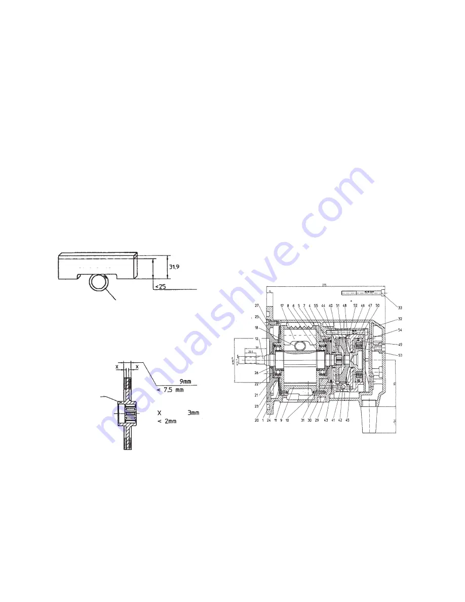
Expendable parts - in particular the vanes - should be
replaced on time. They are worn when their height is less
than 25 mm. We also recommend that the O-Rings (18) that
serve as start-up helps are also be replaced.
One of the main expendable parts are the brake linings (44).
The lining thickness should be controlled at regular intervals
as the wear affects the efficiency of the brake to hold.
The brake disk must be replaced when it's total thickness
becomes less than 7.5 mm or if the brake lining on any side
is less than 2 mm thick.
Disassemble and reassemble the motor
Disassemble - vanes and brake disk
1.) Change vanes (see fig. 20)
Remove the screws (27), end plate (25) and cup spring (24).
With the help of a puller remove the seal plate with bearing
(20) from the rotor. Remove the spacer (23). Remove the
vanes (17) from the rotor slots.
If a puller is not available the complete internal parts can be
removed to be further disassembled on the workbench.
To remove the sealing plates (5) and (20) it can be helpful to
tap the rotor shaft ends on a wooden surface. The motor
cylinder (9) can now be removed and the vanes can be
extracted from the rotor slots. Before replacing new vanes
clean the rotor slots from oil and resin residues. The new
vanes must move freely in the rotor slots (12).
2.) Renew the brake disc
Remove screws (33) and motor end cover (32). Remove
the screws (55).
ATTENTION
: the springs (53) are under
tension. Remove the brake housing cover (54) and springs
(53). Withdraw the air brake housing (46) complete with parts
(47 - 52) from the brake housing (40). Note the O-Ring (45).
Remove the brake disc (44) from the rotor shaft and check
the lining thickness.
Before reassemble clean the brake housing (40) pressure
plate (51) from brake dust.
Coat the rotor shaft end (12, spline) and the inner spline of
the brake disk (44) with an antirust paste (e.g. Altemp Q NB
50) to ensure that the brake disc (44) can move freely on the
rotor (12) spline. Repeat this procedure on the pressure plate
spline (51) and the brake housing (40).
3.) Complete disassembly
Once the motor parts have been removed as described in
1.) and the seal plates (5 and 20) have been removed from
the rotor, the motor cylinder (9) and vanes (17) can been
removed, if required, the bearings (6 and 21) can be removed
from the seal plates (5 and 20) by releasing the circlips (7
and 22). Remove the complete control valve from the motor
body (1). Remove the screws (55) and withdraw the brake
assembly (40 - 54) from the body (1). Remove the O-Ring
(29), seal plate (30) and oil seal (31). Normally the silencer
(2) remains in the body (1) and is only removed if defect.
Original
size
Replace
O-Ring
Brake disk
assy.
Original
Original
Replace
Replace


