10
7.) Functional test
All units with two or more chain strands must be inspected
before initial operation for twisted or kinked chains. Chain
strands may become twisted if the lower block is rolled over.
If a strand is twisted disconnect it from the hoist and re-
thread it correctly. In some cases it may be necessary to
remove the last link
8.) Before initial operation lubricate the unloaded chain and
test all hoist functions under a no-load condition.
6.4 LOAD AND SUSPENSION HOOKS
Inspect the hooks for deformation, damage, surface cracks,
wear and signs of corrosion as required
but at least annu-
ally
. Adverse working conditions may dictate much shorter
periods. Hooks that do not fulfil all requirements must be
replaced immediately. Welding on hooks to compensate for
wear or damage is not permissible. Hooks must be replaced
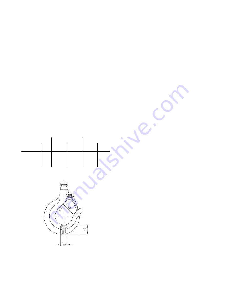
when the mouth of the hook has opened more than 10%
(fig. 14) or the nominal value of other dimensions has de-
creased by 5% due to wear. Nominal dimensions and wear
limits are shown in the following table. Discard all hooks
that do not fulfil all the requirements of the following table.
6.5 TROLLEYS
In particular check following parts:
• Sideplates:
For cracks or deformation in particular around the areas of
screwed connections.
• Trolley wheels:
Visually check for cracks. Wear on trolley wheel flanges.
Grease the transmission.
• Traverses:
In particular around threaded areas for cracks.
• Fasteners:
Check nuts, screws and locking devices for tightness.
6.6 PNEUMATIC HOISTS IN GENERAL
In particular check following parts:
• Threaded connections in general
Check all nuts, screws and locking devices for tightness.
• Chain bin
Ensure the bin is secure. Check for tears or wear
• Suspension bolts
(Connection between hoist and suspension hook resp. trol-
ley)
Check for cracks or wear. Ensure all safety devices are in
place and secure.
6.7 OVERLOAD PROTECTION DEVICE
The overload protection device is factory set to 110%
+/- 10% of the rated lifting capacity and can be checked by
lifting a suitable load. If the device slips at the rated capac-
ity load it can be adjusted as follows (see fig. 19):
Remove the screws (52) that retain the gearbox cover (51).
Loosen the set screw (47) that presses the steel ball (46)
onto the housing. Turn the adjuster (42) clockwise to in-
crease the tension. Re-check the adjustment with a suit-
able load. Secure the set screw (47) with a suitable locking
agent, e.g. loctite 243. Replace the gearbox cover (51) and
secure with screws (52).
6.8 GEARBOX
The gearbox is practically service-free. Service is there-
fore reduced to checking the oil level and changing the oil.
Check oil level
Ensure that the hoist is horizontal and has been stationary
for at least 30 minutes (this allows the oil to drain to the
lower part of the gearbox). Remove the fill-plug. Oil should
be up to the lower edge of the fill hole.
Oil change
The oil (around 0,3 l) is to be changed every 5 years or at
the latest after 400 operating hours.
Remove the screws (52) that retain the gearbox cover (51).
Remove the fill-plug (44). Tip the hoist vertical so that the
oil can drain from the fill hole into a suitable container (can
take up to 30 min.). Replenish the gearbox oil. We recom-
mend a mineral oil viscosity class ISO-VG 460 e.g. FINA
GIRAN L 460. Finally re-adjust the overload protection de-
vice and secure the screw with a locking-agent, e.g. Loctite
241.
CPA 20 / 30
CPA 40 / 50 / 60
Inspection
Dim.
Nominal
[mm]
Limit
[mm]
Nominal
[mm
Limit
[mm]
Hook saddle
b
2
24
22,8
29,5
28
Hook saddle
h
2
35
33,2
44,5
42,3
Mouth
dimension
a
2
43
47,3
54
59,4
Fig. 14


