background image

22

The settings for this feature apply only to the remote control software.

•  Display color memory


You can save the set combination of display colors by clicking and holding  the [

M-1

], [

M-2

] or [

M-

3] button. 

The settings can be recalled by clicking the [

M-1

], [

M-2

] or [

M-3

] button.

Factory settings: 

M-1: COLOR-5, COLOR-13

 M-2

COLOR-9, COLOR-17

 M-3

COLOR-1, COLOR-18

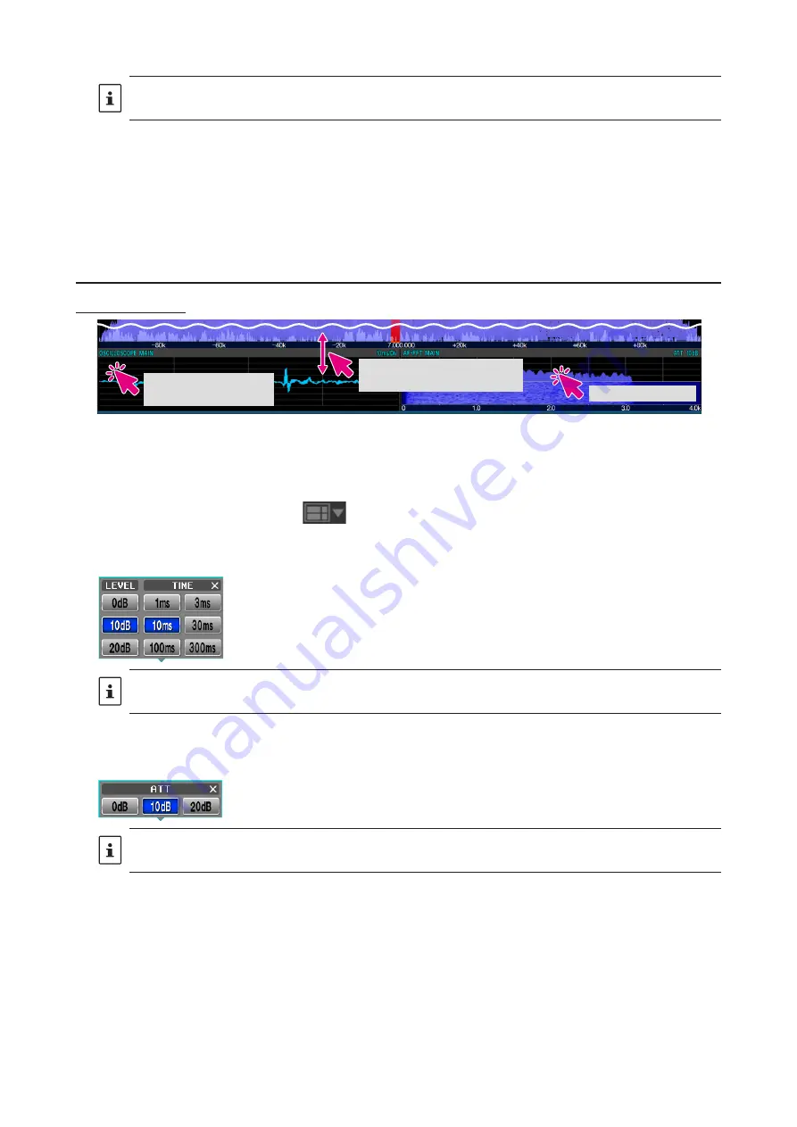
Oscilloscope / AF-FFT area

Screen operation

Change the size of the 

oscilloscope/AF-FFT area

Setting of Level and 

Sweep Speed

Attenuator setting


z

Resize oscilloscope / AF-FFT area

The size* of the oscilloscope / AF-FFT display area can be reduced by dragging the title bar at the top of the 

oscilloscope / AF-FFT area.

*Click and hold the screen layout icon 


at the top of the screen to initialize the size.


z

Click to set the level and sweep speed of the oscilloscope

Click in the oscilloscope display area to set the waveform display level and time axis scale.

The level settings and sweep speed settings are common to the MAIN & SUB band oscilloscope screens.


z

Attenuator setting (AF-FFT)

You can set the attenuator by clicking inside the AF-FFT display area.

The attenuator settings are common to the MAIN band & SUB band AF-FFT screen.

Summary of Contents for SCU-LAN10

Page 1: ...Network Remote Control System SCU LAN10 Operation Manual...

Page 2: ...ric keypad screen 9 Transmitting 10 Functions of screen parts 11 Remote button 11 Screen layout selection button 11 Transmission function button 12 TUNE button 12 VOX button 12 MIC GAIN PROC button 12...

Page 3: ...in Control 28 V M 28 M V 28 V M 28 Memory channel list operation 29 Read memory data from radio 29 Transfer memory data to transceiver 29 Recall memory channel 29 Move memory data to VFO 29 Write to m...

Page 4: ...o open the port of the router and change the settings of the firewall and se curity software Customers are responsible for network security when using this product In communication using a network cha...

Page 5: ...emote control software z z When connecting to the SCU LAN10 for the first time the Connection Setup screen will be displayed automatically Set it by referring to the SCU LAN10 Installation Manual 2 Cl...

Page 6: ...rom the example below z z In the display example below the MULTI button is may be clicked to display the oscilloscope and the AF FFT MAIN band AF FFT Menu bar Screen layout selection button Remote con...

Page 7: ...l is switched Change frequency Switch frequency band 1 Click the MHz digit to display the band selection screen 2 Click the desired band Change frequency There are three ways to change the frequency 1...

Page 8: ...elow that digit with a single touch z z Hz digit 1 When you mouseover the 3 digits of the frequency from 100Hz to 1Hz all the digits of the frequency change to green 2 In this state turning the mouse...

Page 9: ...he keyboard and turn the mouse wheel to increase or decrease the frequency in the set FAST steps When you click on the point you want to receive such as the peak of the signal on the spectrum scope sc...

Page 10: ...U AM AM N FM FM N DATA L DATA U DATA FM D FM N RTTY L RTTY U Transmitting 1 While clicking and holding the PTT button the transceiver will be in transmit status The TX icon is displayed above the fre...

Page 11: ...e a problem with the network line or port open settings Refer to the SCU LAN10 Installation Manual and restart the settings from the beginning Click the warning sign to see the detected issues Screen...

Page 12: ...a tuner VOX button Click Switches VOX ON OFF When ON the button indicator lights red Right click The VOX settings window opens MIC GAIN PROC button Click Switches the PROC ON OFF Only works in LSB USB...

Page 13: ...Click Switches the SPLIT function ON OFF When ON the button is displayed in red Click Hold With the quick split function the SUB band frequency is set to the frequency of the MAIN band the offset freq...

Page 14: ...quency HF 50MHz band or communication mode AM mode and the transmit output of each The maximum transmit power that can be set is less than or equal to the following MAX POWER set in the transceiver se...

Page 15: ...k When the memory group function is ON memory groups are selected in sequence Wheel Selects the memory group when the memory group function is ON Right click Select ON OFF of the memory group function...

Page 16: ...trol z z ENC DEC Turn the tone encoder function or tone squelch function ON z z TONE FREQ Set the tone frequency for the tone encoder function and tone squelch function z z QMB LIST You can check or d...

Page 17: ...down in FAST steps Right click Display the FAST TUNING step setting screen The MAIN SUB bands are swapped If you hold down the SHIFT key on the keyboard and turn the mouse wheel the frequency will in...

Page 18: ...he MAIN band and SUB band display area may be changed by dragging the mouse cursor when it changes to You can initialize the size by clicking and holding the screen layout icon z z Resize the waterfal...

Page 19: ...peed FAST3 sweep speed Fast The settings for this feature apply only to the remote control software SPAN button Sets the frequency span display range of the scope screen Click A popup screen for selec...

Page 20: ...during pause ZIN auto Zero in button While receiving a CW signal in CW mode it can be automatically adjusted zero in to the frequency of the partner station so that it matches the received PITCH pitch...

Page 21: ...rage 2 to 8 Display averaging ON z z The AVERAGING setting is common to the MAIN band SUB band spectrum scope screens z z This function is available only with the remote control software z z 2D HIGH S...

Page 22: ...g z z Resize oscilloscope AF FFT area The size of the oscilloscope AF FFT display area can be reduced by dragging the title bar at the top of the oscilloscope AF FFT area Click and hold the screen lay...

Page 23: ...ion during transmit PO Transmission output display ALC ALC voltage display SWR Antenna SWR display COMP AMC gain control display Compression level display when the speech processor is operating ID Fin...

Page 24: ...CW L CW U AM AM N FM FM N DATA L DATA U DATA FM D FM N RTTY L RTTY U Frequency change operation MHz digit Wheel Move frequency Up down at 1MHz Click Band selection Right Click The numeric keypad scre...

Page 25: ...that digit with one touch Hz digit Wheel Frequency goes up down in TUNING step Click Click the upper half lower half of the number to frequency goes up down the frequency in TUNING steps Drag up and...

Page 26: ...it Click the 5ch or 10ch button to switch the number of QMB channels MAIN SUB SUB MAIN operation Click The frequency data of MAIN band and SUB band are exchanged CLAR Clarifier operation Click Click...

Page 27: ...lifier section to accommodate the connected antenna and the received signal conditions Click Select from IPO AMP1 Approximately 10 dB gain and AMP2 Approximately 20 dB gain R FIL Roofing Filter Switch...

Page 28: ...l list is displayed Click Close the memory channel list M V When the memory channel list is not displayed Click Open the memory channel list When the memory channel list is displayed Click The data sa...

Page 29: ...ays the date and time when the memory data was last read Transfer memory data to transceiver The data of all memory channels stored in the remote control software can be transferred to the transceiv e...

Page 30: ...e erased Editing memory channels You can edit the contents of the memory channel by right clicking the MODE NAME SCAN MEMORY and DISPLAY TYPE fields z z MODE Select the operation mode z z NAME Edit th...

Page 31: ...When the button is blue the IF filter shift frequency can be changed by operating the mouse in the filter function display area Click Hold The IF filter shift frequency returns to 0 Hz When the radio...

Page 32: ...filter function display area NB Noise blanker Click The noise blanker function turns ON OFF Right click The operation setting of the noise blanker function can be changed DNR Digital Noise Reduction...

Page 33: ...ght click The bandwidth of the IF NOTCH filter function can be selected CONT Contour Click The Contour function turns ON OFF Right click The attenuation and bandwidth of the contour function can be se...

Page 34: ...nts Fine adjustments can be made by clicking or on the VC tune bar graph or operating the mouse wheel Also you can click the bar graph to adjust with a slightly larger amount of change RX button When...

Page 35: ...35 PTT Click Hold To transmit Right click To switch the button function between PTT and MOX...

Page 36: ...tup Make settings related to connection with SCU LAN10 There is no need to change it if you have set it once at the beginning While remotely connected to the SCU LAN10 it is grayed out and you can onl...

Page 37: ...bar on the SUB band operation block TX MONI Adjusts the volume of the transmitted audio that is monitored by the monitor function This adjustment is the same as the MONI adjustment bar that appears wh...

Page 38: ...nerates uses and can radiate radio frequency energy and if not installed and used in accordance with the instructions may cause harmful interference to radio communications However there is no guarant...

Page 39: ...roduced without the permission of YAESU MUSEN CO LTD YAESU MUSEN CO LTD Tennozu Parkside Building 2 5 8 Higashi Shinagawa Shinagawa ku Tokyo 140 0002 Japan YAESU USA 6125 Phyllis Drive Cypress CA 9063...

Reviews: