background image

8

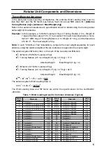
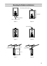
Mounting the Rotator and Antenna

Indoor Performance Check and Alignment

1.  Temporarily connect the rotator unit and the controller using the connection cable prepared 

per the previous section.

2.  Check to be sure that the 

POWER

 switch on the controller is set to OFF, then plug the con-

troller’s AC cable into your  station’s AC outlet.

3.  Set the controller’s 

POWER

 switch to “ON”.  Verify that the controller’s pilot lights have be-

come illuminated.

4.  Hold down the 

LEFT

 (Left rotation) switch, and continue to hold it down until the rotator 

reaches the counter-clockwise position where it automatically stops (“Left” represents 

counter-clock-wise rotation when the rotator is viewed from the top).

5.  When the rotator has reached the left “STOP” position, release the 

LEFT

 switch, and check 

to see if the controller’s indicator needle is pointing to 0º (

N

: North).


If the indicator needle is out of alignment, slightly loosen the needle adjustment screw (using 

a small Phillips screwdriver) on the face of the indicator, then turn the white needle adjust

-

ment knob so that the indicator needle points precisely to 0º.

6.  Just above the round connector jack on the rotator unit, you will observe two raised calibra-

tion marks (one each on the (rotating) bell and (fixed) base of the rotator). These two marks 

should be directly aligned with each other. If not, place a small piece of masking tape on 

the rotating bell and the fixed base of the rotator unit, and make a calibration mark on each 

piece of tape to mark the current position of the bell relative to the base. This calibration 

mark will be used to verify the amount of rotation in the next step.

7.  Hold down the 

RIGHT

 (Right rotation) switch, and continue rotating to the right until the cal-

ibration marks (from Step 6) are again precisely aligned. Now check the indicator needle, 

which should also have rotated fully 360º so as to be pointing exactly to 0º.  
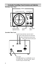
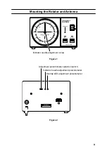
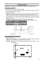
If the indicator 

needle is not pointing exactly to 0º, go to the rear panel of the controller, and set the Adjust

-

ment Potentiometer Selection Switch (see Figure 2) to the 

right

 position. Now use a small 

screwdriver to adjust the Indicator Needle Adjustment Potentiometer (Fig. 2) so that the in

-

dicator needle points exactly to 0º.

8.  After aligning the needle to 0º, set the Adjustment Potentiometer Selection Switch back to 

the 

left

 position.

9.  Hold down the 

RIGHT

 switch again, and continue rotation to the right. You should observe 

the “OVERLAP” LED becoming illuminated as rotation passes the 360º point.  

If the OVER

-

LAP LED does not light up at the 360º position, the Overlap LED Adjustment Potentiometer 

may be used to align the illumination threshold to the 360º point.

10. Check to verify that rotation automatically stops at approximately 90º (East; representing a 

total rotation range of 450º from the original starting point).

11. Press the 

LEFT

 and 

RIGHT

 rotation switches a few more times, verifying that rotation 

appears to be normal. If so, press the 

LEFT

 switch to return the rotator to the fully count-

er-clockwise (0º) position.

12. At this time, you must determine whether you wish to leave the “Left Stop”  position at 

North,or whether you wish to set it to South (to allow uninterrupted rotation from southeast 

to north-east to northwest to southwest, for example).  

If you  wish  to leave  the  “Stop” at 

North, the checkout process is complete. If you wish to set the “Stop” to South, again loos

-

en the needle adjustment screw on the face of the controller, and rotate the needle to the 

“South” position.


Be certain that the rotator is fully rotated to the “LEFT” position in either case.

Advice:

  The position of the “Left Stop” can be set to whatever position you like (North, South, 

East, or West). Just remember where you have set it,  because the antenna must ini-

tially be aimed in the same direction when it is installed on the mast (see next section).

13. Turn the 

POWER

 switch OFF. This completes the ground-based testing of the rotator and 

controller.

Summary of Contents for G-450ADC

Page 1: ...G 450ADC G 450CDC Antenna Rotator Controller User Manual ...

Page 2: ... kgf cm 217 ft lbs Maximum Vertical load Continuous load 100 kg or less Instantaneous load 300 kg Mast Outside Diameter φ32 to φ63 center protrudes by φ48 to φ52 Rotation Range 450 360 Rotation Time approx 56 seconds 20 Antenna K Coefficient 100 Wind Loading Area Pole type 0 5 m2 x 0 5 m Tower type 1 m2 Maximum Continuous Duty 3 minutes Rotor Dimensions and Weight φ186 x 263 mm approx 3 2 kg Contr...

Page 3: ...eved using the GL 33 mast adjustment plate Not supplied with G 450ADC per the illustrations below Mast Diameter φ32 to φ38 Use two plates Mast Diameter φ39 to φ47 Use one plate Mast Diameter φ48 to φ50 Do not use a plate The use of a mast of outside diameter greater than 51 mm 2 01 will result in off center rotation The amount of offset increases with increasing mast diameter A mast of 60 mm outsi...

Page 4: ...verlap indicator LED Indicator needle adjustment screw Left rotation switch Right rotation switch Power Switch 125mm Controller Rear Panel Adjustment potentiometer selection switch Indicator needle adjustment potentiometer Overlap LED adjustment potentiometer Rotor control interconnection jack Fuse holder This holder requires a 1 A G 450ADC or 0 5 A G 450CDC fuse If the fuse is blown replace only ...

Page 5: ...onal nut Rotator Attachment Plate Dimensions 8 4 m m 8 4 m m φ 1 1 9 φ9 4 locations The tower plate onto which the rotator unit is mounted must be drilled with four holes of 9 mm diameter equally spaced on a circle of 119 mm diameter The center to center dis tance between any two adjacent mounting holes is 84 mm ...

Page 6: ...ned weight of antenna plus mast of 10 kg or less and the product of multiplying the Antenna Wind Load Area in m2 by the Height of the Antenna Mast in m must be 0 25 or less see Figure and Table 1 Antenna Weight Mast Weight 10 kg Antenna Wind Load Area Height of Antenna Mast 0 25 Refer to the antenna manufacturer s specification sheet for determining the weight and the surface area of the proposed ...

Page 7: ...1 MHz 3 element Yagi K2 Turning Radius 4 2 m x Weight 7 5 kg 2 5 kg 42 0 Antenna Weight Mast Weight 5 kg 2 KTotal K1 K2 175 42 0 59 5 The antenna system Wind Loading Area is 0 3 m2 0 45 m2 0 75 m2 The Wind Loading Area and K factor are within the specifications for the G 450ADC 450CDC Table 1 Wind Loading Areas for Common Antennas Typical Band MHz Elements Area m2 Band MHz Elements Area m2 7 2 ele...

Page 8: ...ciated with each pin for reference later Pins 1 6 and 7 of the round connector are not used Confirm that all solder joints are firm and cleanly made as this part of the cable will be difficult to access once the rotator is installed on top of the tower Do not slide the shell onto the connector at this time 5 Crimp the supplied pin contacts onto the wires on the opposite end of the cable per the il...

Page 9: ... the wires with solder Make sure to insert the Water Resist Boot first 2 5 3 6 3 4 5 1 2 7 4 Terminal 1 6 and 7 are not used Assembly of 7 pin Metal Connector Pin 1 and 7 of the seven pin metal connector is not used as viewed from pin insertion side as viewed from solder side Wiring for the control cable identical numbers to be connected ...

Page 10: ...s to be pointing exactly to 0º If the indicator needle is not pointing exactly to 0º go to the rear panel of the controller and set the Adjust ment Potentiometer Selection Switch see Figure 2 to the right position Now use a small screwdriver to adjust the Indicator Needle Adjustment Potentiometer Fig 2 so that the in dicator needle points exactly to 0º 8 After aligning the needle to 0º set the Adj...

Page 11: ...ION 5ー NW E 270 300 240 330 210 180 0 90 60 120 30 150 G 450A OFF ON LEFT RIGHT OVERLAP CONTROLLER POWER Indicator needle adjustment screw Figure 1 Adjustment potentiometer selection switch Indicator needle adjustment potentiometer Overlap LED adjustment potentiometer Figure 2 ...

Page 12: ...asher becomes flat then tightened further by 1 2 to one turn maxi mum 6 Install the rotator control cable s round plug into the jack on the side of the rotator s base and tighten the connector ring to secure the connector Slide the rubber boot over the con nector while putting a slight amount of inward pressure on the rubber boot use electrical tape to secure the back end of the rubber boot to the...

Page 13: ...tenna Spring Washer Antenna Mast Mast Bearing GS 065 option Mast Bearing GS 065 option Must be parallel M8 x 16 length 16 mm Figure 3 Figure 4 Figure 5 Figure 6 Figure 7 Figure 8 Provide sufficient slack More than 1 m Less than 1 m ...

Page 14: ...llation of suitable lightning arrestors on all control cables and coaxial lead in cables from your antenna installation See your dealer for details of available light ning protection devices If an electrical storm should be reported in your area quickly unplug the control cable from the rear of the rotator s controller box and disconnect the AC cable from the wall outlet Disconnect the coaxial cab...

Page 15: ...the terminals on the back of the controller etc and make corrections before replacing the 3A fuse on the board inside the controller CAUTION Only replace with a fuse of similar type and rating 3A To measure voltage between terminals remove the connection cable to the rotor Switch Pin Voltage Power switch is in the ON position 4 5 0 V Press the LEFT switch 4 5 DC 22 V Press the RIGHT switch 4 5 DC ...

Page 16: ... cover any impairment caused by tampering misuse failure to follow instructions supplied with the product unauthorized modifications or damage to this product for any reasons such as accident excess moisture lightning power surges connection to improper voltage supply damage caused by inadequate packing or shipping procedures loss of damage to or corruption of stored data product modification to e...

Page 17: ...e decision to repair or replace this product is the sole discretion of YAESU MUSEN Other conditions YAESU MUSEN S MAXIMUM LIABILITY SHALL NOT EXCEED THE ACTUAL PURCHASE PRICE PAID FOR THE PRODUCT IN NO EVENT SHALL YAESU MUSEN BE LIABLE FOR LOSS OF DAMAGE TO OR CORRUPTION OF STORED DATA OR FOR SPECIAL INCIDENTAL CONSEQUENTIAL OR INDIRECT DAMAGES HOW EVER CAUSED INCLUDING WITHOUT LIMITATION TO THE R...

Page 18: ...n bolts and other fasteners sufficiently can be a cause of the antenna and associated equip ment collapsing resulting in a fatal accident or damage to houses or other property CAUTION When installing this product take care not to jam your fingers between parts or cut fingers on edges of parts If the condition of the equipment is abnormal such as emitting smoke or an unusual smell continuing to use...

Page 19: ...t be disposed as household waste Electronic and Electrical Equipment should be recycled at a facility ca pable of handling these items and their waste by products Please contact a local equipment supplier representative or service cen ter for information about the waste collection system in your country ...

Page 20: ...produced without the permission of YAESU MUSEN CO LTD YAESU MUSEN CO LTD Tennozu Parkside Building 2 5 8 Higashi Shinagawa Shinagawa ku Tokyo 140 0002 Japan YAESU USA 6125 Phyllis Drive Cypress CA 90630 U S A YAESU UK Unit 12 Sun Valley Business Park Winnall Close Winchester Hampshire SO23 0LB U K 1907V AS ...

Reviews: