background image

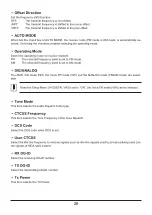
•  Operating Mode

Select the operating mode for receive channel.

FM:   The selected frequency band is set to FM mode.

AM:   The selected frequency band is set to AM mode.

•  DIG/ANALOG

The AMS, V/D mode (DN), the Voice FR mode (VW) and the ANALOG mode (FM/AM mode) are select-

able.

When the Setup Menu [

14 DIGITAL VW

] is set to “

ON

”, the Voice FR mode (VW) can be selected.

• 

Name

Enter the desired memory name (up to 16 digits).

• 

Tone Mode

This item selects the Audio Squelch Code type.

•  CTCSS Frequency

This item selects the Tone Frequency of the Tone Squelch.

• 

DCS Code

Select the DCS code when DCS is set.

• 

User CTCSS

Select the idle line frequency to remove signals such as idle line signals used by private railways and con-

trol signals of MCA radio system.

• 

RX DG-ID

Select the receiving DG-ID number.

• 

TX DG-ID

Select the transmitting DG-ID number

•  Tx Power

This item selects the TX Power.

• 

Step

Sets the channel step for receiving channels. Normally, when a frequency is entered, the optimal channel 

step will be automatically set according to the frequency.

•  Narrow

By ticking the checkbox of this item, switches to the Narrow FM mode. The degree of modulation becomes 

half the normal level.

31

Summary of Contents for ADMS-16

Page 1: ...nient editing of the FTM 500DR DE memory channel frequencies channel information and alpha tags using a personal computer Also the trans ceiver parameters and the setup menu items may be edited and co...

Page 2: ...6 Import 16 Export 16 Import with FTM 100D 400D format 16 Export with FTM 100D 400D format 16 Import with FT2D format 17 Export with FT2D format 17 Import with FT3D format 17 Export with FT3D format 1...

Page 3: ...Offset Direction 30 Operating Mode 31 DIG ANALOG 31 Name 31 Tone Mode 31 CTCSS Frequency 31 DCS Code 31 User CTCSS 31 RX DG ID 31 TX DG ID 31 Tx Power 31 Step 31 Narrow 31 Clock Shift 32 Comment 32 Tr...

Page 4: ...and alerts the user should be aware of This icon indicates helpful notes tips and information Important Notes Before downloading this software please read the Important Notes carefully Copyrights and...

Page 5: ...a USB port on the computer the optional SCU 56 SCU 20 PC connection cable for USB The SCU 56 SCU 20 is included in the optional SCU 58 SCU 40 WIRES X Connection Cable Kit WIRES X Connection Cable Win...

Page 6: ...g ADMS 16 for the first time is as follows ADMS 16 Programming Software Installation 6 page SCU 58 SCU 40 USB Driver Software Installation 8 page Connect the FTM 500DR DE and the PC 8 page Execute ADM...

Page 7: ...MS 16 Programming Software Installation 1 Start up the computer as an Administrator user 2 Double click setup exe in the same folder that con tains the unzip files When the NET Framework install dialo...

Page 8: ...S 16 on a Windows 11 computer is shown below for the purpose of explanation 1 Disconnect the USB Cable from the computer 2 Click the Start button and then click Settings 3 Click Apps 4 Select FTM 500D...

Page 9: ...on of the driver software for the SCU 58 SCU 40 is required Download the driver software for the SCU 58 SCU 40 in advance Download the designated driver software from the Yaesu website https www yaesu...

Page 10: ...microSD memory card with the saved ALL data from FTM 500DR DE to the PC 3 Click Get Data from SD card in the Communications menu then click ALL Select the CLNFTM500D dat file in the FTM500D folder BA...

Page 11: ...ed when starting the ADMS 16 software Menu Bar Click the left mouse button on each Menu in the Menu bar to settings the import export the setting data file get data form FTM 500DR DE and send data to...

Page 12: ...ed memory channels VFO and other preset transceiver settings For more details see Setting the Template Items Set mode screen Basic setting items which are not related to memory channels can be configu...

Page 13: ...4 Click Open 5 Click OK When the data transfer is complete the template screen which was imported from the FTM 500DR DE via the microSD memory card will appear on the ADMS 16 screen This template and...

Page 14: ...lder MEMORY MEMFTM500D dat file in the FTM500D_MEMORY CH folder SETUP SYSFTM500D dat file in the FTM500D folder BACKUP folder Please note that the FTM 500DR DE cannot read the data from the SD card if...

Page 15: ...on is read from the FTM 500D to the ADMS 16 PC programmer See Be sure to read the transceiver data information before using ADMS 16 Page 9 for more information Click the Send Data to FTM 500D paramete...

Page 16: ...he transceiver data information before using ADMS 16 Page 9 for more information When a file saved with an incompatible transceiver is selected an error is displayed and the data cannot be read Close...

Page 17: ...te then import the Memory CSV file Do not edit the Check line at the right side end of the completed CSV file Export To export the data file in the CSV Comma Separated Values format Click the Export p...

Page 18: ...data save the spreadsheet in the CSV comma separated file format FT3D A spreadsheet may be easily created by exporting the template data in the CSV format using the ADMS 11 Export command A separate i...

Page 19: ...grammer click the Exit parameter in the File menu to close the ADMS 16 software If the following pop up screen appears to confirm saving follow the on screen instruction to select the desired button a...

Page 20: ...ter in the Edit menu Copy To copy the data of the selected area to the clipboard click the Copy parameter in the Edit menu Paste To paste the clipboard data to the selected area click the Paste parame...

Page 21: ...ta registered to highest channel to be deleted Continue will appear If you agree click the OK button Delete Channel To delete the specified range of channel data click the Delete Channel parameter in...

Page 22: ...y step Click the OK button to create the additional specified memory channels The 8 33 kHz step is available only when receiving on the Air band 108 136 995 MHz Sort Click the Sort parameter in the Ed...

Page 23: ...he various functions of the FTM 500DR DE according to your preferences The ADMS 16 software displays the set mode menu in an easy to understand manner where you can change and save the setting values...

Page 24: ...e depressed toolbar button and keyboard latch state A check mark appears next to the Status Bar parameter when the Status Bar is displayed Window This menu sets the operating window parameters of the...

Page 25: ...r and edit the frequencies you normally use to the memory channels Up to 999 channels can be registered PMS Edit the upper and lower limit frequencies for performing PMS Programmable Memory Scan Enter...

Page 26: ...not shifted RPT The transmit frequency is shifted to the minus offset RPT The transmit frequency is shifted to the plus offset The transmit frequency is not shifted Operating Mode Select the operatin...

Page 27: ...ift When an internal spurious signal occurs due to the microcomputer clock turn this setting on tick the checkbox This may improve the situation Usually this item is set to OFF un tick the checkbox Co...

Page 28: ...A frequency that is out of the transceiver s range cannot be entered When the error pop up window is opened enter the correct frequency Transmit Frequency The transmit frequency display is grayed out...

Page 29: ...AM The selected frequency band is set to AM mode DIG ANALOG The AMS V D mode DN the Voice FR mode VW and the ANALOG mode FM AM mode are select able When the Setup Menu 14 DIGITAL VW is set to ON the V...

Page 30: ...w By ticking the checkbox of this item switches to the Narrow FM mode Clock Shift When an internal spurious signal occurs due to the microcomputer clock turn this setting on tick the checkbox This may...

Page 31: ...ror pop up window is opened enter the correct frequency Inputting the receive frequency the transmit frequency is automati cally set Offset Frequency When a transmit frequency is not entered transmiss...

Page 32: ...em selects the Tone Frequency of the Tone Squelch DCS Code Select the DCS code when DCS is set User CTCSS Select the idle line frequency to remove signals such as idle line signals used by private rai...

Page 33: ...improve the situation Usually this item is set to OFF un tick the checkbox Comment Comments may be added to the edited HOME channels Up to 255 letters can be used This function is useful in organizing...

Page 34: ...in a different order from the clicked the Send Data to FTM 500D in the Communi cations menu and displayed procedure Follow the on screen instructions The data transmission has stopped before completio...

Page 35: ...eproduced without the permission of YAESU MUSEN CO LTD YAESU MUSEN CO LTD Omori Bellport Building D 3F 6 26 3 Minami Oi Shinagawa ku Tokyo 140 0013 Japan YAESU USA 6125 Phyllis Drive Cypress CA 90630...

Reviews: