


Electrical System
69
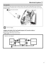
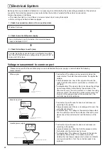
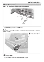
Handle signal
Handle signal
Negative electrode of handle
0.8-3.6V
Multimeter is placed
in DC voltage range
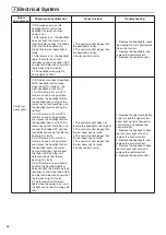
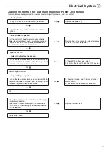
• Test method: open the electric door lock and measure
according to the picture. The voltage is 0.8V without
turning the handle; the greater the turning angle of the
handle, the higher the voltage.
• Failure phenomenon: After the P shift is released, rotate
the handle, and the motor does not work.
• Troubleshooting: This voltage is the feedback voltage of
the handle. When the voltage is abnormal, please check
whether there is any problem with the power supply of the
handle, the wire and the handle.
Brake signal
Brake signal
Negative electrode of handle
Braking status 0V
On the contrary 2.6V
Multimeter is placed
in DC voltage range
• Test method: open the electric door lock and measure
according to the picture. When the brake lever is braked,
the voltage is 0V; when the brake is not braked, 2.6V.
• Failure phenomenon: The brake is constantly powered.
• Troubleshooting: The voltage is output by the controller. If
the voltage is 0V, please check whether the voltage of the
electric door lock line of the controller is normal; whether
the brake switch and the corresponding line are short-
circuited with the negative electrode. If the port still has no
voltage output after removing external influences, please
replace the controller.
Hall Power
Positive electrode of Hall
Negative electrode of Hall
5V
Multimeter is placed
in DC voltage range
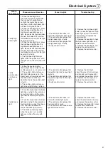
• Test method: open the electric door lock and measure
according to the picture.
• Failure phenomenon: The motor does not rotate.
• Troubleshooting: The 5V voltage is the power supply
voltage provided by the controller to the motor hall. When
the voltage is abnormal, after confirming that the input
voltage is normal, please pull out the Hall plug-in and
directly measure the controller plug-in to confirm, if it is still
abnormal, please replace the controller.
Hall signal
Hall signal
Yellow,green,blue
Negative electrode of Hall
Multimeter is placed
in DC voltage range
5V
......
0
• Test method: open the electric door lock and measure
according to the picture. Turn the motor slowly, the voltage
will be 0V, 5V, 0V... With continuous change.
• Failure phenomenon: The motor does not rotate or rotates
abnormally.
• Troubleshooting: This signal is output by the motor Hall.
Firstly confirm whether the input 5V and the negative
electrode are normal; secondly confirm that the plug is in
good contact; the motor needs to be replaced.
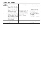
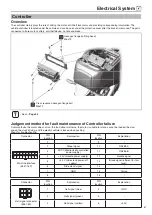
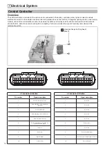
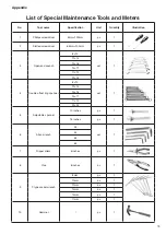
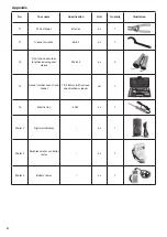
Special Tool
Tool name
Quantity
Application
Gloves
One pair
Wear it during the disassembly and
assembly of the vehicle controller
10mm sleeve
One pc
Use to disassemble the nuts and bolts
8mm sleeve or Phillips screwdriver
One pc
Use to disassemble the nuts and bolts
Summary of Contents for C1S
Page 2: ......
Page 14: ...General Information 12 Rear brake oil pipe Motor line Motor line Motor line...
Page 48: ...MEMO...
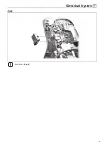
Page 77: ...Electrical System 75 GPS Front Wall Page 21...
Page 87: ......
Page 88: ...2020 06 29 The first revision...


