Frame & Chassis
42
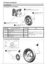
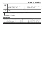
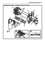
Operation
Order
Operation Name/parts Name
Quantity
Note
1
Brake Pad Guide Pin Bolt
1
2
Brake Pad Dust-proof Cover
1
3
Brake Pad
2
4
Brake Pad Reed
1
5
L/R Pump Body Bolts
2
6
Oil Channel Sealing Ring
2
7
Left Pump Body
1
8
Right Pump Body
1
9
Exhaust Screw
1
10
Piston
2
11
Piston Dust -proof Seal
2
12
Piston Oil Seal
2
When installing, please proceed in the reverse order of disassembly.
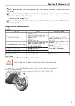
• Before disassembling the caliper, please first discharge the brake fluid in the master cylinder, oil pipe and caliper, and
remove the oil pipe
When disassemble the caliper piston, blow the oil passage hole with compressed air, so that the piston is sent out by air.
Check the wear of the brake pads. If the wear limit is exceeded, replace the front wheel solidity limit. Vertical: 1.0mm
Horizontal: 1.0mm.
Trouble Check for Brake Failure
Number
Possible cause of failure
Repair method
Note
1
Worn brake pads
Replacement beyond wear limit
2
Worn dist brake
Replacement beyond wear limit
3
Air enters brake fluid
Exhaust air
For the CBS configuration, this
operation requires the use of
special tools (vacuum pump) to
exhaust the air.
4
Insufficient brake fluid
Add brake fluid above the lower limit
5
The main pump thruster fails
Replace the main pump thruster
components (professional person)
Replace the main pump
assembly (professional person)
6
Caliper oil seal failure
Replace oil seal (professional person)
Replace caliper assembly
(professional person)
7
Exhausting air bolts loosen
Fastening bolt
8
Damaged brake oil pipe
Replace oil pipe
9
Oil or butter attached to brake pads
Wash brake pads
After the maintenance and replacement of No. 3, 5, 6, 8 , air release operation is required.
Summary of Contents for C1S
Page 2: ......
Page 14: ...General Information 12 Rear brake oil pipe Motor line Motor line Motor line...
Page 48: ...MEMO...
Page 77: ...Electrical System 75 GPS Front Wall Page 21...
Page 87: ......
Page 88: ...2020 06 29 The first revision...

