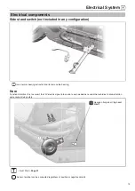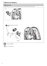
Electrical System
68
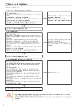
Before performing controller fault detection, it is necessary to confirm whether the under-voltage protection of the vehicle is
caused by the low battery power (no power output when the handle is turned after the vehicle is powered on).
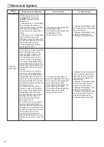
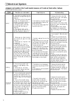
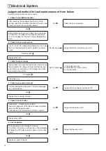
Failure phenomenon: Hall failure
●
The meter fault light is on, and there is no power output when turning the handle.
●
Motor is idling and vibration become bigger.
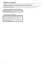
1. Check the connection status of the turnout lead wire
Whether it is loose
2. Check the motor Hall power supply
Use a multimeter to confirm whether the motor Hall power
supply is between 4.2-5V
3. Check Hall voltage to earth jump
Turn the tire lightly by hand and use a multimeter to confirm
that the UVW Hall will have a voltage to earth jump of 2.5V or
more and 0.3V or less.
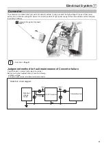
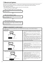
Voltage measurement to common port
*Please make sure that the controller plug-ins are installed and the power supply is normal before the following
measurements.
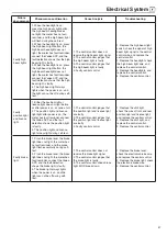
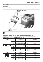
Wheel signal
Wheel signal
0-36V
Connect the negative electrode of
controller power
Multimeter is placed
in DC voltage range
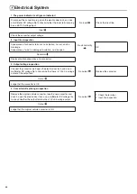
• Test method: The voltage can be tested only when the
motor rotates. The faster the motor rotates, the higher the
voltage.
• Failure phenomenon: Loss of this signal will cause the
motor to rotate without alarm (inclination or vibration will
still alarm).
• Troubleshooting: This signal is the motor phase line voltage
signal transparently transmitted by the controller. If the
above fault occurs, the main problem is to check the wiring
harness contact; if the terminal is pulled out,measure that
there is still no voltage signal at the controller port, the
controller needs to be replaced.
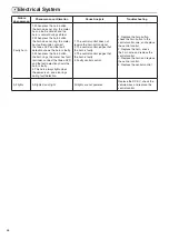
Electric door lock
60V
(
%DWWHU\YROWDJH
)
Connect the negative electrode of
controller power
Electric door lock
Multimeter is placed
in DC voltage range
• Test method: open the electric door lock and measure
according to the picture.
• Failure phenomenon: If there is no voltage at this port, the
controller will not work.
• Troubleshooting: This voltage is the control voltage output
from the central control to the controller. If the fault occurs,
please check the central control and the harness of the
port.
Handle power supply
Negative electrode of handle
4.3V
Multimeter is placed
in DC voltage range
Positive electrode of handle
• Test method: open the electric door lock and measure
according to the picture.
• Failure phenomenon: After the P shift is released, rotate
the handle, and the motor does not work.
• Troubleshooting: This voltage is the power to the handle
provided by the controller . It is necessary to check
whether the input power supply, wire harness and handle
are in good condition; if not, the controller needs to be
replaced.
Summary of Contents for C1S
Page 2: ......
Page 14: ...General Information 12 Rear brake oil pipe Motor line Motor line Motor line...
Page 48: ...MEMO...
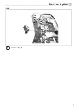
Page 77: ...Electrical System 75 GPS Front Wall Page 21...
Page 87: ......
Page 88: ...2020 06 29 The first revision...


