background image


4.


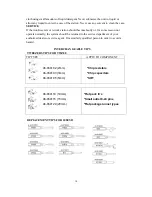
Temperature Correction Setting   
Press “SET” key once when the LED displays “F-2” and flashes that the unit enters 
the Temperature Correction Mode. At this moment, the LED displays preset 
correction value.   


A: Operation of    Centigrade temperature correction

(+99℃~-99℃)


Press “▲” or “▼” key to change the temperature correction value.The first digit 
“— ” means minus (actual temperature is down), “No display” means plus (actual 
temperature is up). 


B: Operation of    Fahrenheit temperature correction value

+178℉~-178℉)


Press “

▲”

  or 

“▼”

key to change the temperature correction value. When the 

numbers is sparkling on LED displays, it means minus value (actual temperature is 

down), when the numbers stop sparkling, it means plus value (actual temperature is 

up). Press “SET” key once to finish the temperature correction and the unit 

automatically backup mode. The user may continue set other modes or back from 

the current setting mode.     


Example for temperature correction: The current set temperature value is 200

,   

however, the actual temperature is only 190

. So it needs to correct by +10

Correction method: if the current correction value is 00 or -00; then change it to 10. 
If the current correction value is -20, then change it to -10. If the current correction 

value is 20, then change it to 30. 


5.


Fahrenheit and Centigrade (Celsius) temperature selection   

When temperature display window shows "F-3" and blinking, press the "SET" 

button, at this time ,the system enters the degrees Fahrenheit and Centigrade 

temperature selection function, indicating the temperature of the window shows 

the current status.   Press "▲" or "▼" key to change the temperature selection 
status. It expressed as degrees Celsius temperature value If set to 

; it shows as 

degrees Fahrenheit temperature if set to 


CARE OF TIPS 

        Caution: 

The soldering iron or tweezer can reach very high temperatures. Be sure 

to turn the unit off prior to carrying out any maintenance or trouble 

shooting steps listed below. 

IMPORTANT 

Remove the tip and clean after moderate to heavy use or at least daily for light usage. 

Remove any loose build up in the tip retaining assembly to prevent tip freezing. 
 

The solder tips supplied are iron clad cooper and if used properly, they should maintain 

optimum life. 

Summary of Contents for LF-1680

Page 1: ...Instruction Manual for Soldering SMD Rework Station LF 1680 For Lead free soldering application and rework on professional SMD electronics ...

Page 2: ...used Keep the soldering tweezers tip and heating element away from the body clothes and flammable material when in operation The soldering tweezers tip and the heating element are still remaining hot after being switched off Ensure that you do not touch the soldering tip and the heating element For your health do not inhale solder fumes You must not undertake work on live parts Only the technician...

Page 3: ...free soldering needs of the electronic production industry and suitable for work on professional SMD electronics An ergonomic handle with shorter distance between heating element and tip gets very fast heat up time and quick heat compensation A high quality sensor and heat transfer technology ensure precise temperature regulation is essential for making consistent reliable soldered connections The...

Page 4: ... out feature by password is convenient for production management The many features of the product make it the ideal tool for service and repair technicians as well as production line soldering operations This unit is developed to meet the present and future lead free soldering needs of the electronic production industry and is ideal for use at any AC outlet BRIEF INTRODUCTION OF PANEL FUNCTIONS Fr...

Page 5: ... Weight Unit only 1 5kg WORKING TEMPERATURE To meet RoHS requirements the 60 40 solder alloys are not allowed in the production process The lead free solder alloys require a working temperature of 30 54 higher than previous generation electrical soldering The working temperature of solder is detailed below and can vary from manufacture to manufacture Melting point 220 428 Normal operation 300 360 ...

Page 6: ...d 2 Tweezers wand 3 Iron holder with brass tip cleaner 4 Tweezers holder with brass tip cleaner 5 AC power cord with plug OPERATING PROCEDURES SOLDER IRON OPERATING PROCEDURES 1 Ensure that the base unit power switch is in the OFF position 2 Plug in Solder wand and connect AC power cord to mains In let 3 Flip the TWZ SIA function switch on to the SIA position 4 Turn Mains power switch to ON positi...

Page 7: ...for use 7 Gently pick up and remove components while ensuring that a vertical pick up and pull out motion is maintained Please note 1 The tweezers temperature will be lower about 50 than the soldering iron temperature at the same temperature setting 2 Use only the approximately designed tips for the job to avoid unnecessary component damage Fig 2 Drawing of Tweezers spares SMD tips for TWZ80 2MM 4...

Page 8: ...crease temperature By pressing key the same procedure as above PARAMETER SETTING 1 Press SET key and hold for at least 4 seconds until display shown sign then release the SET key The sign starts to flash and reminding the user to input the mode lock password 010 fixed If the user inputs the same number as 010 the unit will enter the modes selection procedure otherwise the unit will be back from th...

Page 9: ...re is only 190 So it needs to correct by 10 Correction method if the current correction value is 00 or 00 then change it to 10 If the current correction value is 20 then change it to 10 If the current correction value is 20 then change it to 30 5 Fahrenheit and Centigrade Celsius temperature selection When temperature display window shows F 3 and blinking press the SET button at this time the syst...

Page 10: ...ion 2 Turn the main power switch to the ON position 3 Set temperature to min then turn Coat the tinned surfaces with rosin core solder after reaching 250 482 4 Set to desired temperature after allowing the unit to idle at 250 for 3 minutes 5 The iron will be ready for use once it reaches the preset temperature IMPORTANT Remove and clean the tip daily If a new tip is installed remove any loose buil...

Page 11: ...not operate normally the system should be returned to the service department of your authorized dealer or service agent Or a similarly qualified person in order to avoid a hazard INTERCHANGEABLE TIPS TWEEZERS TIPS FOR TWZ80 TIP TYPE APPLY TO COMPONENT REPLACEMENT TIPS FOR 108ESD 46 060102 2mm 46 060103 3mm 46 060105 5mm Chip resistors Chip capacitors SOT 46 060110 10mm 46 060115 15mm 46 060120 20m...

Reviews: