


System 182-XT-4
Installation
3 - 21
ba76027e02
12/2014
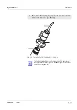
Fig. 3-14 Connecting the SACIQ cable with the IQ sensor
3
Then, screw the coupling ring (2) of the IQ sensor connection
cable on the IQ sensor up to the stop.
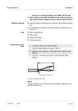
For further instructions on the mounting of IQ sensors at
the application location, please see the respective manuals
(immersion depths, etc.).
SACIQ
1
2
Summary of Contents for YSI 182-XT-4
Page 6: ...Contents System 182 XT 4 0 4 ba76027e02 12 2014...
Page 10: ...Overview System 182 XT 4 1 4 ba76027e02 12 2014...
Page 14: ...Safety System 182 XT 4 2 4 ba76027e02 12 2014...
Page 64: ...Installation System 182 XT 4 3 50 ba76027e02 12 2014...
Page 82: ...Operation System 182 XT 4 4 18 ba76027e02 12 2014...
Page 88: ...The SETTINGS menu System 182 XT 4 5 6 ba76027e02 12 2014...
Page 114: ...Relay outputs System 182 XT 4 6 26 ba76027e02 12 2014...
Page 116: ...Maintenance and cleaning System 182 XT 4 7 2 ba76027e02 12 2014...
Page 122: ...What to do if System 182 XT 4 8 6 ba76027e02 12 2014...
Page 134: ...Technical data System 182 XT 4 9 12 ba76027e02 12 2014...
Page 135: ...System 182 XT 4 1 ba76027e02 12 2014...
Page 138: ...Accessories and options System 182 XT 4 11 2 ba76027e02 12 2014...
Page 142: ...Appendix store separately if required System 182 XT 4 13 2 ba76027e02 12 2014...
Page 143: ......


