51
4 Description and use of software
4.1 Display
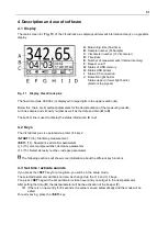
The main screen (
Fig. 11
) of the ViscoClock
plus
displays all relevant information clearly on a graphics
display.
Fig. 11 Display ViscoClock plus
The flow time (max. 999.99 s) is displayed in large digits in the upper section (
A
).
Below this, there are important parameters for the documentation of the measuring results,
such as sample and viscosity number as well as the date and time (
B
to
D
).
The bottom line is used to display the status information (
E
to
J
).
4.2 Keys
The ViscoClock
plus
is operated via a total of 4 keys:
<START>
(16): Start/stop measurement
<SET>
(14): Save/print, set/confirm parameters
<↓>
(13): elect sample number, decrease parameters
<↑>
(15): Select viscosity number, increase parameters
The following sections will show more information about the different key functions.
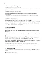
4.3 Set time / activate sounds
If you press the
<SET>
key for a long time, you will be in the setup mode.
The selected parameter will blink and can be changed via the
<↑>
and
<↓>
keys.
You press
<SET>
again: the set parameter is taken over and you will get to the next parameter.
After setting the time (
D
), the last parameter will be the activation of the beeper (
F
).
If there is no new entry for 8 seconds, the value is saved automatically and the mode will be
exited.
For early saving, press the
<SET>
key.
A
: Measuring time (flow time)
B
: Sample number (S=Sample)
C
: Viscometer number (V=Viscometer)
D
: Time/date
E
: Number of measurements (internal memory)
F
: Beeper on/off
G
: Status of USB memory
H
: Status USB printer
I
: Status PC connection
J
: Detection light barrier:
Status upper or lower light barrier
(start or stop signal).
Summary of Contents for SI Analytics ViscoClock plus
Page 1: ...OPERATING MANUAL ViscoClock plus VISCOSITY MEASURING DEVICE...
Page 33: ......
Page 34: ......
Page 35: ......


