Xylem Lowara e-IXPS Installation, Operation And Maintenance Instructions Download Page 31

en – Original instructions 


e-IXPS - Installation, Operation and Maintenance Instructions 

31


7.5


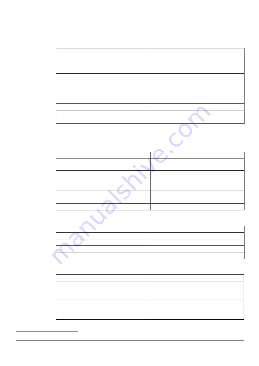
The thermal overload protection triggers or the fuses trip 

The motor thermal overload protection triggers or the fuses trip when the unit starts.


Cause 

Solution 

It is calibrated at a value too low in relation to the rated 
current of the motor 

Recalibrate 

Missing power supply phase 

Check the power supply and restore the phase 

Loose and/or faulty connections of the thermal overload 

protection 

Tighten or replace the clamps and terminals 

Loose and/or incorrect and/or faulty (star-delta) connections 

in the terminal board of the motor 

Tighten or replace the clamps and terminals 

Motor (coil) faulty 

Check and repair or replace the motor 

Pump unit mechanically seized 

Check and repair the pump unit 

Check valve faulty 

Replace the check valve 

Foot check valve faulty 

Replace the foot valve 

7.6


The thermal overload protection triggers 

The motor thermal overload protection triggers occasionally, or after the unit has been 

running for a few minutes. 

Cause 

Solution 

It is calibrated at a value too low in relation to the rated 
current of the motor 

Recalibrate 

Input voltage outside the rated limits 

Make sure the voltage values are correct 

Unbalanced input voltage 

Make sure the voltage of the three phases is balanced 

Wrong duty point, flow rate above the permitted limits 

Bring the flow rate back within the permitted limits 

Liquid too thick 

Check the liquid 

Room temperature too high 

Decrease the temperature 

Unit faulty  

Contact Xylem or the Authorised Distributor 

7.7


The motor becomes excessively hot 

Cause 

Solution 

Room temperature too high 

Decrease the temperature 

Motor cooling fan damaged 

Replace the cooling fan 

Too many starts 

See paragraph 7.10 

Frequency converter wrongly calibrated (if present) 

See the frequency converter manual 

7.8


Little or no hydraulic performance 

Cause 

Solution 

Three-phase motor turning in the wrong direction 

Check the direction of rotation and change if necessary 

Incorrect priming (there are air bubbles in the suction pipe or 
in the unit) 

Repeat the priming procedure 

Cavitation 

Increase the NPSH

3

 available in the system 

Check valve blocked or partially clogged 

Replace the check valve 

Piping and/or unit clogged 

Remove the clogging 


3

 Net Positive Suction Head 

Summary of Contents for Lowara e-IXPS

Page 1: ...e IXPS Pumps according to ISO 2858 and ISO 5199 Installation Operation and Maintenance Instructions Applicare qui l adesivo con il codice a barre Apply the adhesive bar code nameplate here ...

Page 2: ...age 10 2 3 1 Storage of the packed unit 11 2 3 2 Long term storage of the unit 11 2 3 3 Return 11 3 Description of the Product 12 3 1 Features 12 3 2 Data plates 13 3 3 Identification code 13 3 4 Part names 14 4 Installation 15 4 1 General precautions 15 4 2 Mechanical installation 15 4 2 1 Precautions 15 4 2 2 Installation area 15 4 2 3 Installation on concrete foundation 15 4 3 Hydraulic connect...

Page 3: ...al overload protection triggers or the fuses trip 31 7 6 The thermal overload protection triggers 31 7 7 The motor becomes excessively hot 31 7 8 Little or no hydraulic performance 31 7 9 When switched off the unit turns in the opposite direction 32 7 10 The unit starts and stops too frequently 32 7 11 The unit does not stop 32 7 12 The unit is leaking at the mechanical seal 32 7 13 The frequency ...

Page 4: ...s 4 e IXPS Installation Operation and Maintenance Instructions 9 3 WEEE UK 39 10 Declarations 40 10 1 EC Declaration of Conformity Original 40 10 2 UKCA Declaration of Conformity Original 41 11 Warranty 43 11 1 Information 43 ...

Page 5: ... may be supplied with supplementary instruction manuals For situations not considered in the manual or in the commercial documentation contact Xylem or the Authorised Distributor 1 2 Hazard levels and safety symbols Before using the unit the user must read understand and comply with the indications of the danger warnings in order to avoid the following risks Injuries and health hazards Damage to t...

Page 6: ...the unit Inexperienced users WARNING For EU countries this product may be used by children aged 8 years and above and persons with reduced physical sensory or mental capabilities or who lack experience and knowledge provided that they are supervised and have been instructed on how to use it safely and understand the hazards involved Children must not play with the product Cleaning and maintenance ...

Page 7: ...n hazard If the unit has been exposed to ionizing radiations implement the necessary safety measures for the protection of people If the unit needs to be dispatched inform the carrier and the recipient accordingly so that appropriate safety measures can be put in place 1 5 Spare parts WARNING Replace all worn or faulty components with original spare parts to prevent unit malfunction and personal i...

Page 8: ...the unit CAUTION Cut and abrasion hazard Always wear personal protective equipment 1 Remove the packaging 2 Ensure sorting of all packaging materials in accordance with the applicable regulations 3 Release the unit by removing the screws and or cutting the straps if fitted 4 Check the unit for integrity and to make sure that there are no missing components 5 In case of damage or missing components...

Page 9: ...or slings hereinafter referred to as ropes hooks and or clasps hereinafter referred to as hooks shackles or eyebolts that comply with the applicable directives and are suitable for use WARNING It is forbidden to use the shaft end and or the motor eyebolts to move the unit NOTE Make sure that the harnessing does not hit and or damage the unit WARNING Lift and handle the unit slowly to avoid stabili...

Page 10: ...e 3 Lift the crane and tension the ropes without lifting the unit Lifting and positioning 1 Lift and move the unit slowly 2 Set the unit down slowly 3 Release the harness 2 3 Storage Precautions WARNING risk of injury Pay attention to liquids that are excessively hot or cold WARNING Make sure that the drained liquid cannot cause damage or injuries WARNING It is prohibited to dispose of lubricant l...

Page 11: ...ns for the storage of the packed unit Note This operation is essential in environments with cold temperatures Otherwise any residual liquid in the unit could have an adverse effect on its condition and performance For more information on long term storage contact the Xylem sales company or Authorised Distributor 2 3 3 Return 1 Correctly empty the unit 2 Wash and clean the unit especially if used t...

Page 12: ...systems Washers Galvanic processes and painting systems Cleaning of tanks and cisterns Mixing of liquids Water movement in water parks Observe the operating limits in Technical Information on page 24 DANGER Potentially explosive atmosphere hazard It is prohibited to start the unit in environments with potentially explosive atmospheres or with combustible dusts if it has no EX approval Pumped liqui...

Page 13: ...name 2 Size from 40 25 160 to 300 250 315 3 Impeller with full A reduced B C or D standard or special X diameter 4 Motor power in kWx10 5 WEG W ABB A or other manufacturers X 6 2 pole 2 4 pole 4 or 6 pole 6 motor 7 Frequency 50 Hz 5 or 60 Hz 6 8 Standard operating pressure discharge side PN 16 bar B PN 25 bar C class 150 R or class 300 S 9 Cast ductile iron D stainless steel N or duplex R pump bod...

Page 14: ...ons 3 4 Part names 1 Discharge body volute casing 2 Bolt 3 Lifting lug 4 Motor adapter 5 Plug 6 Impeller 7 Wear ring 8 Impeller key 9 Impeller nut 10 Plug 11 Plug 12 O ring 13 Casing cover 14 Mechanical seal 15 Stub shaft 16 Motor XIPS_M0002_A_sc 2 3 1 5 6 8 10 11 7 12 13 14 9 15 4 16 ...

Page 15: ...ble 4 2 2 Installation area 1 Follow the provisions in Operating environment on page 33 2 Place the unit in a raised position in relation to the floor 3 Check that the air clearance between the wall and the motor fan grid is 100 mm 4 in to ensure suitable ventilation 300 mm 12 in to allow inspection and removal of the motor 4 Make sure that any leaks will not cause flooding to the installation are...

Page 16: ...on the shaft and discharge port the maximum permitted tolerance is 0 2 mm m 0 0024 in ft 6 Align the suction and discharge ports to their piping 7 If necessary insert levelling shims between the plate and the foundation 8 Tighten the nuts on the tie rods evenly and fully Hexagon nut Torque Nm lbf in M12 60 44 M16 120 89 M20 200 148 M24 350 258 M27 530 391 DANGER Explosion due to static charge Ensu...

Page 17: ... the hydraulic system 1 Support the piping system independently to prevent them from weighing on the unit 2 Remove any welding residues deposits and impurities from the piping system in order to avoid damage to the unit the method and duration of the cleaning operation must be adapted to the materials of the unit and the gaskets 3 To reduce the transmission of vibrations between the unit and the s...

Page 18: ...3 1050 945 1836 613 438 508 908 80 788 718 875 1379 560 403 455 826 100 65 100 1173 1050 945 1836 613 438 508 908 65 648 595 735 1146 525 385 420 775 125 80 125 1383 1243 1120 2170 735 525 665 1122 80 788 718 875 1379 560 403 455 826 125 100 125 1383 1243 1120 2170 735 525 665 1122 100 1050 945 1173 1836 613 438 508 908 150 125 150 1750 1575 1418 2748 875 613 718 1287 125 1243 1120 1383 2170 735 5...

Page 19: ...mage to the unit 1 Suction port 2 Discharge port 3 G 1 4 recirculation outlet optional 4 G 1 4 suction pressure port 5 G 1 4 discharge pressure port 6 G 1 2 drain 4 4 Mechanical seals and auxiliary systems 1 Find the type of seal by reading the third and second last letters of the identification code 2 Follow the instructions and the API PLAN standards in the table based on the type Designation Ty...

Page 20: ...hazard Install suitable systems for protection against indirect contact in order to prevent lethal electric shocks 4 5 2 Guidelines for electrical connection 1 Check that the electrical leads are protected against High temperature Vibrations Collisions Liquids 2 Check that the power supply line is provided with A short circuit protection device of appropriate size 4 5 3 Motor connection 1 Open the...

Page 21: ...ency converter manufacturers The converter exposes the insulation of the motor to a greater load determined by the length of the connecting cable observe the requirements of the Manufacturer of the frequency converter For applications requiring silent operation install an outlet filter between the motor and the converter a sinusoidal filter can reduce the noise even further The bearings of the mot...

Page 22: ...uxiliary control circuit DANGER Electrical hazard If the unit is connected to the frequency converter disconnect the mains power supply and wait at least 10 minutes for the residual current to dissipate WARNING Always wear personal protective equipment WARNING Always use suitable working tools WARNING Injuries hazard Check that the protection devices are installed when applicable risk of physical ...

Page 23: ...alues given in the data sheet and or order confirmation As they can occur with too fast shut down keep them under control for example by installing a non return valve on the pressure side fly wheel or air tanks They can cause temperature shock and damage or impair the operation of single components Permitted Nozzle loads and Torques The suction and discharge piping must be designed in such way tha...

Page 24: ...of the motor 2 Start the unit 3 Check the rotation direction through the motor cover 4 Stop the unit 5 In case of incorrect rotation direction Disconnect the power supply Invert two of the three wires of the power supply cord 6 Check the direction of rotation again 5 4 Start up DANGER Overheating of fluid due to closed discharge valves Do not keep the on off valve on the discharge side in the clos...

Page 25: ...omatic restart may only take place if it is made sure that the pump remains filled with liquid when it is at a standstill Operation limits Flow min max If no other data are given in the performance curves or data sheet the following is valid Qmin 0 1 x QBEP for short term operation Qmin 0 3 x QBEP for continuous operation Qmax 1 2 x QBEP for continuous operation1 QBEP Flow in best efficiency point...

Page 26: ...uired DANGER Sparks can occur during servicing work Always perform maintenance work on explosion proof pumps away from potentially explosive atmospheres WARNING Always wear personal protective equipment WARNING Always use suitable working tools DANGER Electrical hazard Before starting work check that the electric power supply is disconnected and locked out to avoid unintentional restart of the uni...

Page 27: ...eral information Type of maintenance Purpose Interval Check Check That there are no unwanted noise or vibrations The mechanical seal That there are no liquid leaks from the gaskets The tightness of screws and bolts The motor adapter The filter in the suction pipe for clogging clean as necessary Daily Check Check the temperature of the motor bearings Check the operation of the device in standby Eve...

Page 28: ...without mechanical impediments NOTE If the unit has not been used for more than 2 years replace the grease in the bearings 6 4 Spare parts ordering Identify the spare parts with the product codes directly on the site www lowara com spark Contact Xylem or the Authorised Distributor for further technical information 6 5 Tightening torques Block pump with bolted casing cover Position number Bolt size...

Page 29: ...nstallation Operation and Maintenance Instructions 29 920 01 M12x1 5 50 440 Torque wrench M16x1 5 80 710 M20x1 5 120 1060 M24x2 0 170 1500 922 02 M16X1 5 80 710 Torque wrench M20X1 5 100 900 M24X2 130 1150 M30X2 180 1600 M36X2 220 1950 ...

Page 30: ... against the absence of liquid has tripped Check the liquid level in the tank and or Adjust the device If the problem continues replace the device Control panel faulty Check and repair or replace the control panel Unit faulty Contact Xylem or the Authorised Distributor 7 3 The differential protection device RCD has tripped Cause Solution Motor leaking Check and repair or replace the motor Differen...

Page 31: ...Solution It is calibrated at a value too low in relation to the rated current of the motor Recalibrate Input voltage outside the rated limits Make sure the voltage values are correct Unbalanced input voltage Make sure the voltage of the three phases is balanced Wrong duty point flow rate above the permitted limits Bring the flow rate back within the permitted limits Liquid too thick Check the liqu...

Page 32: ...nstall an expansion vessel Oversized unit Contact Xylem or the Authorised Distributor 7 11 The unit does not stop The unit with automatic start and stop device never stops Cause Solution The required flow rate is greater than the one expected Reduce the required flow rate Discharge pipe leaking Eliminate the leaks Three phase motor turning in the wrong direction Check the direction of rotation and...

Page 33: ...r manufacturer s instructions and catalogues to reduce the power output of the motor or replace it with a more powerful model Altitude m ft Power reduction coefficient 1000 1500 3300 4900 0 97 1500 2000 4900 6600 0 95 8 2 Temperature of pumped liquid The table shows the permitted liquid temperatures according to the material of the standard non balanced seal with elastomeric bellow Seal material M...

Page 34: ... RN 25 bar 363 psi only ASME B16 5 DN NN UU RR TT RN 25 bar 363 psi only 8 4 Electrical specifications See the motor data plate Permitted tolerances for the supply voltage Frequency Hz Phase No of conductors earth UN V 50 1 2 1 220 240 6 3 3 1 230 400 10 400 690 10 60 1 2 1 220 230 6 3 3 1 220 380 5 380 660 10 ...

Page 35: ...5 71 5 70 5 70 0 74 8 71 6 71 2 55 72 4 71 4 76 9 72 7 75 73 8 72 9 78 7 74 1 90 74 8 73 8 79 7 74 8 8 7 Construction and maintenance data Model Diameter of ports mm in Shaft diameter mm in Mechanical seal mm in Suction Discharge 40 25 160 40 25 200 40 1 1 2 25 1 24 0 94 33 1 30 40 25 250 40 1 1 2 25 1 32 1 26 43 1 69 50 32 160 50 32 200 50 2 32 1 1 4 24 0 94 33 1 30 50 32 250 50 2 32 1 1 4 32 1 2...

Page 36: ...4 42 1 65 53 2 09 150 125 200 150 125 250 150 125 315 150 125 400 150 6 125 5 42 1 65 53 2 09 200 150 200 200 150 250 200 8 150 6 42 1 65 53 2 09 200 150 315 200 150 400 200 8 150 6 48 1 89 65 2 56 250 200 250 250 200 315 250 10 200 8 48 1 89 65 2 56 300 250 315 300 12 250 10 48 1 89 65 2 56 8 8 Section drawings and list of components 8 8 1 Drawings To find the drawing corresponding to your model ...

Page 37: ...iece motor adapter 8 8 2 List of components Code Description 102 01 Volute casing 161 01 Casing cover 210 10 Stub Shaft 230 01 Impeller 341 01 Motor adapter 341 02 Motor size adapter 400 01 Gasket 411 01 Gasket 411 02 Gasket 411 03 Gasket 411 04 Gasket 411 05 Gasket 411 06 Gasket 411 07 Gasket 412 01 O Ring 433 01 Mechanical seal unbalanced 502 01 Wear ring XIPS_M0009_A_sc ai ...

Page 38: ...otor 900 01 Lifting lug 901 12 Hexagon head screw 901 13 Hexagon head screw 901 14 Hexagon head screw 902 01 Stud 902 02 Stud 902 09 Stud 902 14 Stud 903 01 Plug 903 02 Plug 903 03 Plug 903 04 Plug 903 05 Plug 903 06 Plug 903 07 Plug 904 07 Set screw 904 08 Set screw 904 09 Set screw 914 13 Socket head cap screw 920 01 Hexagon nut 920 02 Hexagon nut 920 09 Hexagon nut 920 14 Hexagon nut 922 01 Imp...

Page 39: ... then contact the producer and follow the system that it has adopted to allow the separate collection of equipment at the end of life or select an organization independently authorized to manage waste 9 3 WEEE UK INFORMATION TO USERS pursuant to art 44 of the The Waste Electrical and Electronic Equipment Regulations 2013 S I 2013 No 3113 The crossed bin symbol on the appliance or on its packaging ...

Page 40: ...2 1 2014 Signed for and on behalf of Xylem Service Italia S r l Montecchio Maggiore 23 06 2022 Marco Ferretti Chairman of the Board of Directors rev 00 EU Declaration of Conformity n 59 1 EMC Apparatus Product model see the label on the Safety and Other Information manual RoHS Unique identification of the EEE IXP 2 Name and address of the manufacturer Xylem Service Italia S r l Via Vittorio Lombar...

Page 41: ...res that the product Electric pump unit see the label on the Safety and Other Information manual fulfils the relevant provisions of the following UK legislative acts S I 2008 1597 Supply of Machinery Safety Regulations 2008 and subsequent amendments Schedule 2 Part 2 ANNEX II natural or legal person authorised to compile the technical file Xylem Service Austria GmbH Ernst Vogel Strasse 2 2000 Stoc...

Page 42: ...to the relevant designed standards used or references to the other technical specifications in relation to which conformity is declared EN 61000 6 1 2007 EN IEC 61000 6 1 2019 EN 61000 6 2 2005 EN IEC 61000 6 2 2019 EN 61000 6 3 2007 A1 2011 EN IEC 61000 6 3 2021 EN 61000 6 4 2007 A1 2011 EN IEC 61000 6 4 2019 EN IEC 63000 2018 7 Approved body 8 Additional information RoHS Annex III of 2011 65 EU ...

Page 43: ...en Original instructions e IXPS Installation Operation and Maintenance Instructions 43 11Warranty 11 1 Information For information on the warranty refer to the commercial documentation ...

Page 44: ...o the environment and we help people use water efficiently in their homes buildings factories and farms In more than 150 countries we have strong long standing relationships with customers who know us for our powerful combination of leading product brands and applications expertise backed by a legacy of innovation For more information on how Xylem can help you go to www xylem com Xylem Service Ita...

Reviews: