


25
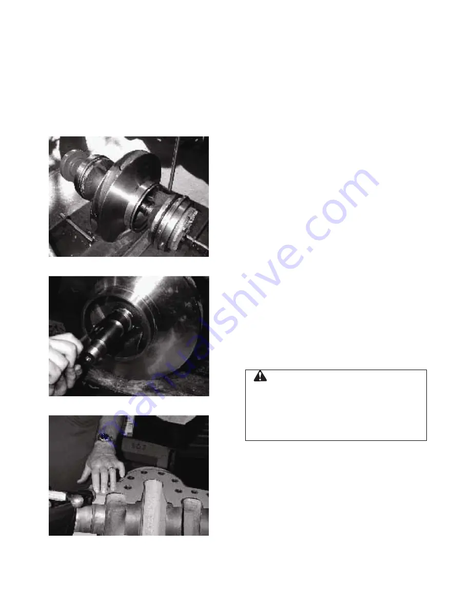
(Instead of heating the impeller, you may
press impeller off the shaft, if press is
available.)
NOTE:
Press away from the coupling end.
NOTE:
For impellers with replaceable rings;
remove the rings, if necessary, by cutting with a
cold chisel.
16. Remove the impeller key from the shaft.
Figure 21: Rotating Element
Figure 22: Removing Impeller Retaining Ring
Figure 23: Trimming Casing Gasket
REASSEMBLING THE PUMP
(when removing the rotating element of the pump
is required)
NOTE:
All bearings, O-rings, lip-seals, mechanical
seals, gaskets, impeller rings, and casing rings
should be replaced with the new parts during
assembly. All reusable parts should be cleaned of
all foreign matter before reassembling. The main
casing joint gasket can be made using the upper
and lower half as a template. Lay the gasket
material on the casing joint. Trim the gasket by
lightly tapping with a ball peen hammer so that it is
flush with the inside edges of the casing. See
Figure 23. Do not hit casing edge with hammer
hard enough to round edge.
NOTE:
Precut-casing gaskets can be ordered to
minimize the amount of trimming.
1. Before assembling the rotating element
prepare the casing and install the casing
gaskets to the parting line.
2. Clean the gasket surfaces of the casing. Apply
Scotch 3M-77 spray adhesive or equivalent to
the lower half of the casing.
3. Within one minute of spraying, set the
untrimmed gaskets in place on the lower half
of the casing, align the holes in the gaskets
with the holes in the casing, and press the
gaskets firmly against the lower half of the
casing face in the area coated by the
adhesive.
4. Trim the gaskets
flush
with the lower casing
bores. See Figure 23.
CAUTION
Machined-casing bores must remain sharp at the
casing parting line. Gaskets must be flush with the
bore in order to contact O-rings. Leakage can
result around the stuffing box O-ring if this step is
not properly followed.
5. Assemble the impeller key in the shaft key
slot.
NOTE:
For impeller with replaceable rings, heat
each new ring (approximately 300°F-400°F for
bronze) and slide onto the impeller. Using gloves,
hold rings against the impeller shoulder until cool.
6. Check the impeller and casing to determine
the correct relationship. Heat the impeller
evenly to 300°F maximum to expand the bore.


