


10
T.I.R., while a satisfactory angular
misalignment is .004" T.I.R. per inch of
radius R. See Figure 8.
Final Alignment
Final alignment cannot be accomplished until
the pump has been operated initially for a
sufficient length of time to attain operating
temperature. When normal operating
temperature has been attained, secure the
pump to re-check alignment and compensate
for temperature accordingly. See the section
entitled Alignment Procedure.
WARNING: Rotating Components
Hazard
Do not operate pump without all guards in
place.
Failure to follow these instructions could
result in serious personal injury or death, or
property damage.
OPTIONAL Alignment Procedure
If desired, the pump and motor feet can be
doweled to the base after final alignment is
complete. This should not be done until the
unit has been run for a sufficient length of
time and alignment is within the tolerance.
See the section entitled Doweling.
CAUTION: Extreme Temperature
and/or Flying Debris Hazard
Eye protection and gloves required.
Failure to follow these instructions could
result in property damage and/or moderate
personal injury.
NOTE:
Pump may have been doweled to base at
factory.
DOWELING
Dowel the pump and driving unit as follows:
a. Drill holes through diagonally opposite feet
and into the base. Holes must be of a
diameter 1/64 inch less than the diameter of
the dowel pins. Clean out the chips.
b. Ream the holes in feet and base to the proper
diameter for the pins (light push fit). Clean out
the chips.
c. Insert pins to be approximately flush with feet.
SUCTION AND DISCHARGE PIPING
When installing the pump piping, be sure to
observe the following precautions:
Piping should always be run to the pump.
Do not move pump to pipe. This could make final
alignment impossible.
Both the suction and discharge piping should be
supported independently near the pump and
properly aligned, so that no strain is transmitted to
the pump when the flange bolts are tightened. Use
pipe hangers or other supports at necessary
intervals to provide support. When expansion
joints are used in the piping system, they must be
installed beyond the piping supports closest to the
pump. Tie bolts should be used with expansion
joints to prevent pipe strain. Do not install
expansion joints next to the pump or in any way
that would cause a strain on the pump resulting
from system pressure changes. It is usually
advisable to increase the size of both suction and
discharge pipes at the pump connections to
decrease the loss of head from friction.
Install piping as straight as possible, avoiding
unnecessary bends. Where necessary, use 45-
degree or long sweep 90-degree fitting to
decrease friction losses.
Make sure that all piping joints are air-tight.
Where flanged joints are used, assure that inside
diameters match properly.
Remove burrs and sharp edges when making up
joints.
Do not “spring” piping when making any
connections.
Provide for pipe expansion when hot fluids are to
be pumped.
Suction Piping
When installing the suction piping, observe
the following precautions. See Figure 9.
The sizing and installation of the suction
piping is extremely important. It must be
selected and installed so that pressure losses
are minimized and sufficient liquid will flow
into the pump when started and operated.
Many NPSH (Net Positive Suction Head)
problems can be attributed directly to
improper suction piping systems.
11
CHECK VALVE
GATE VALVE
INCREASER
CORRECT
C OF PIPE
SUCTION PIPE INSTALLED WITH
A GRADUAL RISE TO PUMP
L
LEVEL
AIR POCKET
INCORRECT
AIR POCKET
INCORRECT
AIR POCKET
INCORRECT
GRADUAL RISE
TO PUMP
NO AIR
POCKETS
CORRECT
NO AIR
POCKETS
GRADUAL RISE
TO PUMP
ECCENTRIC
REDUCER
CORRECT
DISTANCE PLUS
ECCENTRIC REDUCER
STRAIGHTENS FLOW
CORRECT
PATH OF
WATER
INCORRECT
Figure 9: Suction Pipe Installations
(Piping supports not shown)
Friction losses caused by undersized suction
piping can increase the fluid’s velocity into the
pump. As recommended by the Hydraulic
Institute, Standard ANSI/HI 1.1-1.5-1994,
suction pipe velocity should not exceed the
velocity in the pump suction nozzle. In some
situations pipe velocity may need to be
further reduced to satisfy pump NPSH
requirements and to control suction line
losses. Pipe friction can be reduced by using
pipes that are one to two sizes larger than the
pump suction nozzle in order to maintain pipe
velocities less than 5 feet/second.
Suction piping should be short in length, as direct
as possible, and never smaller in diameter than
the pump suction opening. If the suction pipe is
short, the pipe diameter can be the same size as
the suction opening. If longer suction pipe is
required, pipes should be one or two sizes larger
than the opening, depending on piping length.
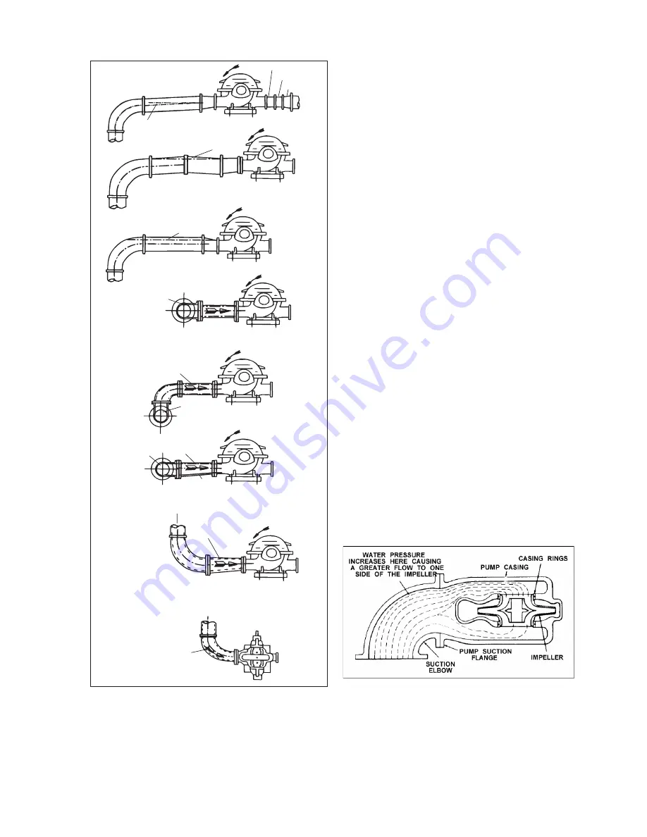
Suction piping for horizontal double suction pumps
should not be installed with an elbow close to the
suction flange of the pump, except when the
suction elbow is in the vertical plane. A suction
pipe of the same size as the suction nozzle,
approaching at any angle other than straight up or
straight down, must have the elbow located 10
pipe diameters from the suction flange of the
pump. Vertical mounted pumps and other space
limitations require special piping.
There is always an uneven turbulent flow around
an elbow. When it is in a position other than the
vertical it causes more liquid to enter one side of
the impeller than the other. See Figure 10. This
results in high unequalized thrust loads that will
overheat the bearings and cause rapid wear, in
addition to affecting hydraulic performance.
Figure 10: Unbalanced loading of a double
suction impeller due to uneven flow
around an elbow adjacent to the pump


