


19.Product weight
20.Locked rotor code letter
21.Power factor
22.Maximum ambient temperature
23.Read installation manual
24.Notified body, only for EN-approved Ex products
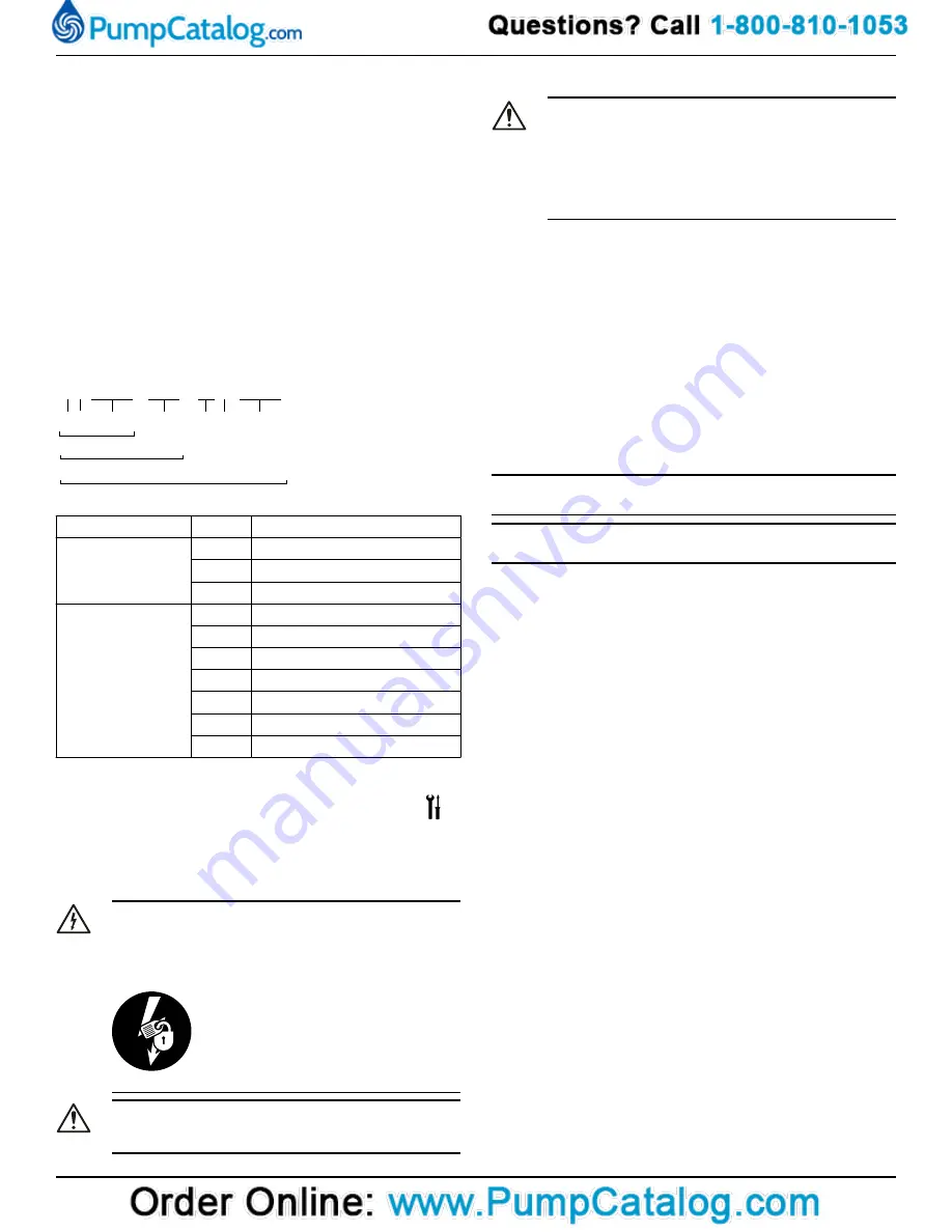
25.WEEE-Directive symbol
Figure 1: The data plate
3.5 Product denomination
Reading instruction
In this section, code characters are illustrated accordingly:
X = letter
Y = digit
The different types of codes are marked up with a, b and c. Code pa-
rameters are marked up with numbers.
Codes and parameters
XXYYYY YYY YYY YYYY
1 2
3
4
5 6
7
a
b
c
WS006265B
.
Type of Callout
Number Indication
Type of code
a
Sales denomination
b
Product code
c
Serial number
Parameter
1
Hydraulic end
2
Type of installation
3
Sales code
4
Version
5
Production year
6
Production cycle
7
Running number
4 Installation
4.1 Precautions
Before starting work, make sure that the safety instructions in the chap-
ter
on page 3 have been read and understood.
DANGER: Electrical Hazard
Before starting work on the unit, make sure that the unit and
the control panel are isolated from the power supply and
cannot be energized. This applies to the control circuit as
well.
DANGER: Inhalation Hazard
Before entering the work area, make sure that the atmos-
phere contains sufficient oxygen and no toxic gases.
4.1.1 Hazardous atmospheres
DANGER: Explosion/Fire Hazard
Special rules apply to installations in explosive or flammable
atmospheres. Do not install the product or any auxiliary
equipment in an explosive zone unless it is rated explosion-
proof or intrinsically-safe. If the product is rated explosion-
proof or intrinsically-safe, then see the specific explosion-
proof information in the safety chapter before taking any fur-
ther actions.
General requirements
These requirements apply:
• Use the pump dimensional drawing in order to ensure proper in-
stallation.
Before installing the pump, do the following:
• Provide a suitable barrier around the work area, for example, a
guard rail.
• Make sure that equipment is in place so that the unit cannot roll or
fall over during the installation process.
• Check the explosion risk before you weld or use electric hand tools.
• Check that the cable and cable entry have not been damaged dur-
ing transport.
• Always remove all debris and waste material from the sump, inlet
piping, and discharge connection, before you install the pump.
• Always check the impeller rotation before lowering the pump into
the pumped liquid.
NOTICE:
Do not run the pump dry.
NOTICE:
Never force piping to make a connection with a pump.
Authority regulation
Vent the tank of a sewage station in accordance with local plumbing
codes.
Fasteners
• Only use fasteners of the correct size and material.
• Replace all corroded or damaged fasteners.
• Make sure that all the fasteners are correctly tightened and that
there are no missing fasteners.
4.1.2 Install with Wet well installation
In the wet-well installation, the pump is installed on a stationary dis-
charge connection, and operates either completely or partially sub-
merged in the pumped liquid. These requirements and instructions on-
ly apply when the installation is made according to the dimensional
drawing.
1310 Installation, Operation, and Maintenance Manual
7
Summary of Contents for GOULDS 2GFK2412H
Page 1: ...Installation Operation and Maintenance Manual 90002801_3 0 1310...
Page 2: ......
Page 23: ......


