


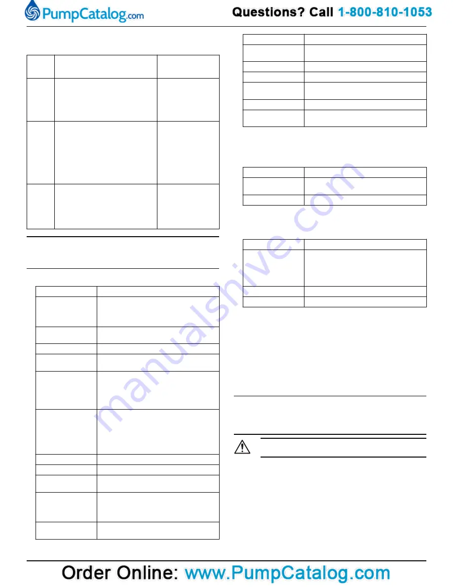
6.3 Service the pump
Type of
mainte-
nance
Purpose
Inspection interval
Initial in-
spection
A Xylem-authorized personnel
checks the pump condition. From
the results, the personnel recom-
mends the intervals for the periodi-
cal inspection and overhaul for the
installation.
Within the first year of
operation.
Periodi-
cal in-
spection
The inspection prevents operational
interruptions and machine break-
downs. The measures to increase
performance and pump efficiency
are decided for each application.
They can include such things as im-
peller trimming, wear part control
and replacement, control of zinc-an-
odes and control of the stator.
Up to every year
Applies to normal ap-
plications and operat-
ing conditions at me-
dia (liquid) tempera-
tures <40°C (104°F).
Over-
haul
The overhaul lengthens the operat-
ing lifetime of the product. It in-
cludes the replacement of key com-
ponents and the measures that are
taken during an inspection.
Up to every two years
Applies to normal ap-
plications and operat-
ing conditions at me-
dia (liquid) tempera-
tures <40°C (104°F).
NOTICE:
Shorter intervals may be required when the operating conditions are
extreme, for example with very abrasive or corrosive applications or
when the liquid temperatures exceed 40°C (104°F).
6.3.1 Inspection
Service item
Action
Cable
1. If the outer jacket is damaged, then re-
place the cable.
2. Check that the cables do not have any
sharp bends and are not pinched.
Connection to power Check that the connections are properly se-
cured.
Electrical cabinets
Check that they are clean and dry.
Impeller
1. Check the impeller clearance.
2. Adjust the impeller, if necessary.
Stator housing
1. Drain all liquid, if any.
2. Check the resistance of the leakage sen-
sor.
Normal value approximately 1530 ohms,
alarm approximately 330 ohms.
Insulation
Use a megger maximum 1000 V.
1. Check that the resistance between the
ground (earth) and phase lead is more
than 5 megohms.
2. Conduct a phase-to-phase resistance
check.
Junction box
Check that it is clean and dry.
Level regulators
Check the condition and functionality.
Lifting device
Check that the local safety regulations are
followed.
Lifting handle
1. Check the screws.
2. Check the condition of the lifting handle
and the chain.
3. If necessary, replace.
O-rings
1. Replace the coolant plug O-rings.
2. Grease the O-rings.
Service item
Action
Personnel safety de-
vices
Check the guard rails, covers, and other
protections.
Rotation direction
Check the impeller rotation.
Oil housing
Fill with new coolant, if necessary.
Terminal block/
closed end splice
Check that the connections are properly
tightened/connected.
Thermal contacts
Normally closed circuit; interval 0–1 ohm.
Voltage and amper-
age
Check the running values.
6.3.2 Overhaul
The basic repair kit includes O-rings, seals, and bearings.
For an overhaul, do the following in addition to the tasks listed un-
der Inspection.
Service item
Action
Support and main
bearing
Replace the bearings with new bearings.
Mechanical seal
Replace with new seal units.
6.3.3 Service in case of alarm
For information about indication values for sensors, see
Alarm source
Action
LD
1. Check for liquid in the stator housing.
2. Drain all liquid, if any.
3. Check the mechanical seal unit, the O-
rings, and the cable entry, if liquid was
found.
Thermal contact
Check the start and stop levels.
Overload protection Check that the impeller can rotate freely.
6.4 Replace the impeller
Required tools:
• 6 hexagon bit adapter with an extension of at least 125 mm (4.92
in.)
• Impeller puller
If applicable, contact your local sales and service representative for
correct type and size.
• Rod (wood or copper) for locking the impeller in place, if applica-
ble.
• Two crowbars, if applicable
NOTICE:
• When laying the pump on its side, do not allow the weight of the
pump to rest on any portion of the impeller. The impeller must not
be allowed to make contact with the concrete floor or other hard
and rough surfaces.
CAUTION: Cutting Hazard
Worn parts can have sharp edges. Wear protective clothing.
6.4.1 Remove the impeller: Non-clog and Vortex (H, M)
The instruction applies to pumps equipped with a Non-clog impeller or
a Vortex impeller with pressure class H or M.
1. Remove the suction cover:
a) Place the pump horizontally.
b) Remove the suction cover screws.
c) Remove the suction cover from the pump housing.
2. Remove the impeller:
a) Remove the impeller screw.
b) Remove the impeller and the conical sleeve.
1310 Installation, Operation, and Maintenance Manual
15
Summary of Contents for GOULDS 2GFK2412H
Page 1: ...Installation Operation and Maintenance Manual 90002801_3 0 1310...
Page 2: ......
Page 23: ......


