background image

Xyclop user manual for 16 channel network video recorder 
------------------------------------------------------------------------------------------------------------------------------------------ 


22 


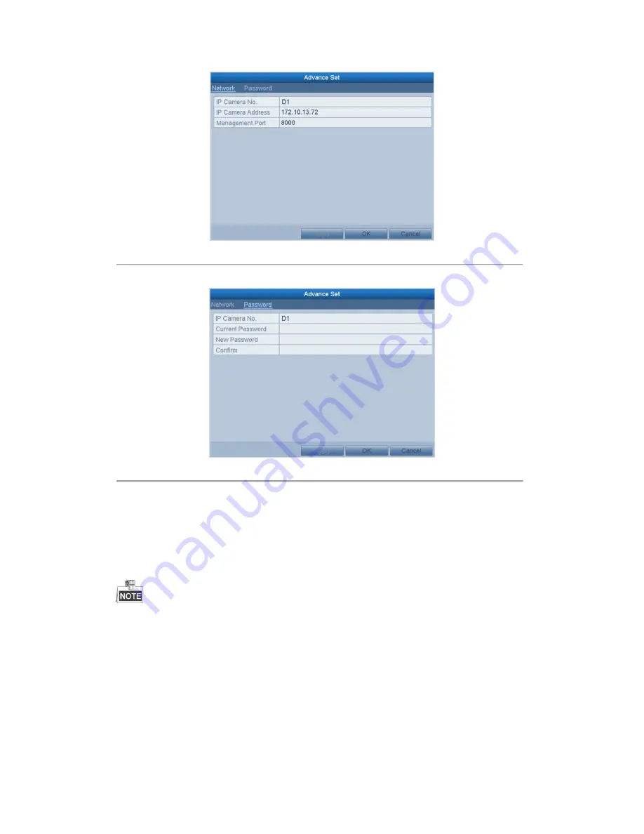
Figure 2. 16


Network Configuration of the Camera 


2.


You can edit the network information and the password of the camera. 


Figure 2. 17


Password Configuration of the Camera 


3.


Click 

Apply

 to save the settings and click 

OK

 to exit the interface. 


2.3.3


Editing IP Cameras Connected to the PoE Interfaces 


The PoE interfaces enables the NVR system to pass electrical power safely, along with data, on Ethernet cabling to 

the connected network cameras. 

The  XC-16CH-NVR-4TB  NVR  provides  up  to  16  PoE  interfaces  which  can  connect  to  16  network  cameras 

directly; and if  you disable the PoE interface,  you can also connect to the online network cameras. And the PoE 

interface supports the Plug-and-Play function. 

Example: 

When you want to connect 2 online cameras and connect 6 network cameras via PoE interfaces, you must disable 2 

PoE interfaces in the Edit IP Camera menu. 

To add Cameras for NVR supporting PoE function: 

Before you start: 

Summary of Contents for XC-16CH-NVR-4TB

Page 1: ...Xyclop Network Video Recorder User Manual XC 16CH NVR 4TB Username admin Password 12345 Xyclop user manual for 16 channel network video recorder V1 0 0...

Page 2: ...y interference received including interference that may cause undesired operation EU Conformity Statement This product and if applicable the supplied accessories too are marked with CE and comply ther...

Page 3: ...ual are for reference only This manual is applicable to the XC16CH NVR 4TB Product Key Features General Connectable to network cameras network dome and encoders Connectable to the smart IP cameras PAL...

Page 4: ...i channel Supports pause play reverse speed up speed down skip forward and skip backward when playback and locating by dragging the mouse Up to 16 ch synchronous playback at 4CIF real time Manual capt...

Page 5: ...ort of device parameters Remote viewing of the device status system logs and alarm status Remote keyboard operation Remote locking and unlocking of control panel and mouse Remote HDD formatting and pr...

Page 6: ...e View 27 3 2 2 Using the Mouse in Live View 27 3 2 3 Using an Auxiliary Monitor 28 3 2 4 Quick Setting Toolbar in Live View Mode 28 3 3 Adjusting Live View Settings 31 3 4 Channel zero Encoding 33 3...

Page 7: ...7 Backup 82 7 1 Backing up Record Files 82 7 1 1 Backing up by Normal Video Search 82 7 1 2 Backing up by Event Search 87 7 1 3 Backing up Video Clips 90 7 2 Backing up Pictures 92 7 3 Managing Backup...

Page 8: ...tializing HDDs 136 10 2 Managing Network HDD 137 10 3 Managing eSATA 139 10 4 Managing HDD Group 140 10 4 1 Setting HDD Groups 140 10 4 2 Setting HDD Property 141 10 5 Configuring Quota Mode 143 10 6...

Page 9: ...llation of the NVR 1 Keep all liquids away from the NVR 2 Install the NVR in a well ventilated and dust free area 3 Ensure environmental conditions meet factory specifications 4 Install a manufacturer...

Page 10: ...e direction to open the front panel 2 Fasten the hard disk mounting handle to the hard disk with screws 3 Slide the HDD into the NVR with the label up and the connectors on the rear of the HDD 4 Repea...

Page 11: ...indicator turns yellow when system is running Status Status indicator blinks red when data is being read from or written to HDD Tx Rx TX RX indictor blinks yellow when network connection is functionin...

Page 12: ...tch RS 485 termination switch Up position is not terminated Down position is terminated with 120 resistance NOT SUPPORTED 10 RS 485 Interface Connector for RS 485 devices T and T pins connect to R and...

Page 13: ...your provider The operation of the mouse Table 1 1 Description of the Mouse Control Name Action Description Left Click Single Click Live view Select channel and show the quick set menu Menu Select an...

Page 14: ...1 Soft Keyboard 1 Figure 1 2 Soft Keyboard 2 Description of the buttons on the soft keyboard Table 1 2 Description of the Soft Keyboard Icons Icon Description Icon Description Number English letter Lo...

Page 15: ...device gets the power supply 2 Press the POWER button on the front panel The Power indicator LED should turn blue indicating that the unit begins to start up 3 After startup the Power indicator LED re...

Page 16: ...or Basic Configuration By default the Setup Wizard starts once the NVR has loaded as shown in Figure 2 2 Figure 2 2 Start Wizard Interface Operating the Setup Wizard 1 The Setup Wizard can walk you th...

Page 17: ...the given fields 5 Click the Next button to enter the date and time settings window as shown in Figure 2 4 Figure 2 4 Date and Time Settings 6 After the time settings click Next button which takes yo...

Page 18: ...utton You enter the Adding IP Camera interface 9 Click Search to find online IP Camera Select the IP camera to be added and click the Add button Figure 2 7 Search for IP Cameras 10 Click Next button C...

Page 19: ...d and correct For detailed checking and configuring of the network please see Chapter Checking Network Traffic and Chapter Configuring Network Detection OPTION 1 Steps 1 Right click the mouse when you...

Page 20: ...mation of camera Delete the IP camera Advanced settings of the camera Upgrade the added IP camera 4 To add other IP cameras 1 Click the Custom Adding button to pop up the Add IP Camera Custom interfac...

Page 21: ...eters of the camera Add the detected IP camera The camera is connected you can click the icon to get the live view of the camera The camera is disconnected you can click the icon to get the exception...

Page 22: ...the IP address protocol and other parameters Figure 2 15 Edit the Parameters Channel Port If the connected device is an encoding device with multiple channels you can choose the channel to connect by...

Page 23: ...VR system to pass electrical power safely along with data on Ethernet cabling to the connected network cameras The XC 16CH NVR 4TB NVR provides up to 16 PoE interfaces which can connect to 16 network...

Page 24: ...t the camera is connected to the PoE interface so in this case the parameters of the camera can t be edited The IP address of the camera can only be edited in the Network Configuration interface see C...

Page 25: ...P address of the camera can only be edited in the Network Configuration interface When connecting the XC FE6 360F IR camera you are able to support up to 5 streams 1 fish eye stream 1 panaromic stream...

Page 26: ...icons at the upper right of the screen for each channel showing the status of the record and alarm in the channel so that you can know whether the channel is recorded or whether there are alarms occu...

Page 27: ...Main output switch the NVR checks the connection of the output interfaces to define the main and auxiliary output interfaces The priority level for the main and aux output is HDMI VGA CVBS This means...

Page 28: ...just the screen layout by choosing the corresponding icon Switch to the previous next screen Enable disable the auto switch of the screens Start continuous recording or motion detection recording of a...

Page 29: ...o Playback mode PTZ Enter PTZ Control mode Main Monitor Enter Main operation mode In the live view mode of the main output monitor the menu operation is not available while Aux output mode is enabled...

Page 30: ...the area to zoom in as shown in Figure 3 3 Figure 3 3 Digital Zoom Image Settings icon can be selected to enter the Image Settings menu You can to set the image parameters according to the actual dema...

Page 31: ...ual for 16 channel network video recorder 30 Figure 3 5 Live View Strategy Move the mouse onto the icon to show the real time stream information including the frame rate bitrate and resolution Figure...

Page 32: ...include Video Output Interface Designates the output to configure the settings for Outputs include HDMI depends on the model VGA Main CVBS and Spot Output Live View Mode Designates the display mode t...

Page 33: ...ision modes are supported 2 Select the small window and double click on the channel number to display the channel on the window You can click button to start live view for all the channels and click t...

Page 34: ...fecting the image quality channel zero encoding is supported as an option for you Steps 1 Enter the Live View Settings interface Menu Configuration Live View 2 Select the Channel Zero Encoding tab Fig...

Page 35: ...view mode and if you want to do some operation you need to enter user name and password tog in again Steps 1 Enter the Shutdown menu Menu Shutdown Figure 3 10 Shutdown 2 Click Logout After you have l...

Page 36: ...re you control the PTZ camera Before you start Check that the PTZ and the NVR are connected properly through RS 485 interface Steps 1 Enter the PTZ Settings interface Menu Camera PTZ Figure 4 1 PTZ Ge...

Page 37: ...e PTZ camera to point to when an event takes place Steps 1 Enter the PTZ Control interface Menu Camera PTZ More Settings Figure 4 2 PTZ More Settings 2 Use the directional button to wheel the camera t...

Page 38: ...all Preset 3 Choose the preset number Call preset in live view mode Steps 1 Click the button PTZ in the lower right corner of the PTZ setting interface Or press the PTZ button on the front panel or cl...

Page 39: ...such as the key point No duration of staying for one key point and speed of patrol The key point is corresponding to the preset The Key Point No determines the order at which the PTZ will follow while...

Page 40: ...PTZ More Settings 2 Select the patrol number and then click to call the patrol 3 Click to stop it Figure 4 9 Calling Patrol Calling patrol in live view mode Steps 1 Click the button PTZ in the lower r...

Page 41: ...ake the PTZ movement according to the predefined path Steps 1 Enter the PTZ Control interface Menu Camera PTZ More Settings 2 Choose pattern number in the option box Figure 4 11 PTZ Pattern 3 Click an...

Page 42: ...setting menu in live view mode 2 And then choose Pattern on the control bar 3 Double click the pattern or select the pattern and click to call it 4 3 PTZ Control Panel To enter the PTZ control panel...

Page 43: ...scription Icon Description Icon Description Direction button and the auto cycle button Zoom Focus Iris Zoom Focus Iris The speed of the PTZ movement Light on off Wiper on off 3D Zoom Image Centralizat...

Page 44: ...a HDD and initialize it Menu HDD General Figure 5 1 HDD General 2 Check the storage mode of the HDD 1 Click Advanced to check the storage mode of the HDD 2 If the HDD mode is Quota please set the max...

Page 45: ...ed the file will be deleted You can set the expired time to 0 and then the file will not be deleted The actual keeping time for the file should be determined by the capacity of the HDD Redundant Recor...

Page 46: ...the camera 3 Click Apply to save the settings 4 Parameters Settings for Capture 1 Select the Capture tab Figure 5 5 Capture Parameters 2 Configure the parameters 3 Click Apply to save the settings The...

Page 47: ...ing and capture To schedule the automatic capture you need to choose the Capture tab in the Schedule interface Steps 1 Enter the Record Schedule interface Menu Record Capture Schedule 2 Configure Reco...

Page 48: ...alarm M A motion and alarm and VCA Video Content Analysis triggered recording and capture you must configure the motion detection settings alarm input settings or VCA settings as well For detailed in...

Page 49: ...shown in the figure below Figure 5 11 Descriptions of the color icons II Click the Apply button to validate the settings 3 Optional If the settings can also be used to other channels click Copy and th...

Page 50: ...surveillance center and so on In this chapter you can follow the steps to schedule a record which triggered by the detected motion Steps 1 Enter the Motion Detection interface Menu Camera Motion Figu...

Page 51: ...ich you want the motion detection event to trigger recording 6 Click Apply to save the settings 7 Click OK to back to the upper level menu 8 Exit the Motion Detection menu 3 Edit the Motion Detection...

Page 52: ...m triggered recording or capture Steps 1 Enter the Alarm setting interface Menu Configuration Alarm Figure 5 16 Alarm Settings 2 Click Alarm Input Figure 5 17 Alarm Settings Alarm Input 1 Select Alarm...

Page 53: ...o back to the upper level menu Repeat the above steps to configure other alarm input parameters If the settings can also be applied to other alarm inputs click Copy and choose the alarm input number F...

Page 54: ...ual Or press the REC SHOT button on the front panel Figure 5 20 Manual Record 2 Enable the Manual Recording 1 Select Record on the left bar 2 Click the status button before camera number to change to...

Page 55: ...Xyclop user manual for 16 channel network video recorder 54 Green icon means that the channel is configured the capture schedule After rebooting all the continuous capture will be canceled...

Page 56: ...ording and capture on holiday Steps 1 Enter the Record setting interface Menu Record Holiday Figure 5 22 Holiday Settings 2 Enable Edit Holiday schedule 1 Click to enter the Edit interface Figure 5 23...

Page 57: ...r 16 channel network video recorder 56 6 Click OK to exit the Edit interface 3 Enter Record Capture Schedule settings interface to edit the holiday recording schedule See Chapter 6 2 Configuring Recor...

Page 58: ...igure 5 24 HDD General 2 Select the HDD and click to enter the Local HDD Settings interface 1 Set the HDD property to Redundancy Figure 5 25 HDD General Editing 2 Click Apply to save the settings 3 Cl...

Page 59: ...58 Figure 5 26 Record Parameters 2 Select Camera you want to configure in the drop down list 3 Check the checkbox of Redundant Record Capture 4 Click OK to save settings and back to the upper level me...

Page 60: ...eft side menu 4 Click to enter editing interface 5 Configuring HDD group 1 Choose a group number for the HDD group 2 Click Apply and then in the pop up message box click Yes to save your settings 3 Cl...

Page 61: ...yback interface Menu Playback 2 Check the checkbox of channel s in the channel list and then double click to select a date on the calendar Figure 5 29 Normal Playback 3 During playback click the butto...

Page 62: ...change it to to unlock the file and the file is not protected Lock File when Export Steps 1 Enter Export setting interface Menu Export Figure 5 31 Export 2 Select the channels you want to investigate...

Page 63: ...t completed cannot be locked 2 Click to change it to to unlock the file and the file is not protected Figure 5 33 Unlocking Attention 5 9 2 Setting HDD Property to Read only Steps 1 Enter HDD setting...

Page 64: ...ad only HDD If you want to save files in the HDD change the property to R W If there is only one HDD and is set to Read only the NVR can t record any files Only live view mode is available If you set...

Page 65: ...e using the mouse and click the button in the quick setting toolbar In the instant playback mode only record files recorded during the last five minutes on this channel will be played back Figure 6 1...

Page 66: ...icates the start end time of the record About video type bar represents normal recording manual or schedule represents event recording motion alarm motion alarm motion alarm VCA Playback progress bar...

Page 67: ...ed in specified time duration Multi channel simultaneous playback and channel switch are supported Steps 1 Enter playback interface Menu Playback 2 Check the checkbox of channel s in the channel list...

Page 68: ...s bar to locate special frames and drag the cursor to show the thumbnail of the current time Table 6 2 Detailed Explanation of Playback by time Interface Button Operation Button Operation Button Opera...

Page 69: ...d motion detection Steps 1 Enter the Playback interface Menu Playback 2 Select the Event in the drop down list on the top left side 3 Select Alarm Input Motion or VCA as the event type edit the Start...

Page 70: ...5 Click button to play back the file You can click the Back button to back to the search interface Pre play and post play can be configured 6 Playback interface The toolbar in the bottom part of Playb...

Page 71: ...d tag File Management Digital Zoom Pause reverse play Reverse play Single frame reverse play Stop Pause play Play Single frame play 30s forward 30s reverse Speed down Speed up Previous day Next day Sc...

Page 72: ...video file 3 Tag management 1 Click button to enter the file management interface 2 Click the Tag tab and you can check edit and delete tag s Figure 6 13 Tag Management Interface Steps 1 Select the T...

Page 73: ...72 Figure 6 14 Video Search by Tag 3 Click button to play back the file You can click the Back button to back to the search interface Pre play and post play can be configured Figure 6 15 Interface of...

Page 74: ...5 Smart Playback Purpose The smart playback function provides an easy way to get through the less effective information When you select the smart playback mode the system will analyze the video contai...

Page 75: ...h 5 Set the smart search rules Intrusion Detection Click the button and then specify 4 points to set a quadrilateral region for intrusion detection Only one region can be set Motion Detection 1 Click...

Page 76: ...o click any point of the progress bar to locate special frames Table 6 5 Detailed Explanation of Smart Playback Button Operation Button Operation Button Operation Smart search Stop Pause play Play Pro...

Page 77: ...with record file and click button to enter Playback interface If there is no record file at the time point of the log the message box No result found will pop up Figure 6 21 Result of System Log Searc...

Page 78: ...ck files in the external devices Steps 1 Enter Playback interface Menu Playback 2 Select the External File in the drop down list on the top left side The files are listed in the right side list You ca...

Page 79: ...e reverse playback of the record file click button until the speed changes to Single frame and one click on the playback screen represents reverse playback of one frame It is also feasible to use butt...

Page 80: ...d as example to describe the following settings Steps 1 Enter Playback interface Menu Playback 2 Check more than one checkboxes to select multiple channels and click to select a date on the calendar F...

Page 81: ...Menu Playback 2 Select the Picture in the drop down list on the top left side Figure 6 26 Interface of Playback by Picture 3 Choose channels edit start time and end time and then click Search to show...

Page 82: ...bottom part of Playback interface can be used to control playing process Figure 6 28 Picture Playback Toolbar Table 6 6 Detailed Explanation of Picture playback Toolbar Button Function Button Function...

Page 83: ...lash drives and USB HDDs Steps 1 Enter Export interface Menu Export Normal 2 Set search condition and click Search button to enter the search result interface Figure 7 1 Normal Video Search for Backup...

Page 84: ...Click the Refresh button Reconnect device Check for compatibility from vendor You can also format USB flash drives or USB HDDs via the device Figure 7 3 Export by Normal Video Search using USB Flash D...

Page 85: ...igure 7 6 Normal Video Search for Backup 3 Select record files you want to back up Click button to play the record file if you want to check it Check the checkbox before the record files you want to b...

Page 86: ...interface until all record files are exported with pop up message box Export finished Figure 7 10 Export Finished 6 Check backup result Choose the record file in Export interface and click button to...

Page 87: ...record file if you want to check it Tick record files you want to back up The size of the currently selected files is displayed in the lower left corner of the window Figure 7 12 Result of Normal Vid...

Page 88: ...on Stay in the Exporting interface until all record files are exported with pop up message Export finished Figure 7 15 Export Finished 6 Check backup result Choose the record file in Export interface...

Page 89: ...ck Search button to enter the Search Result interface Event types contain Alarm Input Motion and VCA we take export by alarm input as an example Figure 7 16 Event Search for Backup 2 Select record fil...

Page 90: ...nt to back up and click Export button to enter Export interface If the inserted USB device is not recognized Click the Refresh button Reconnect device Check for compatibility from vendor You can also...

Page 91: ...ayback interface Please refer to Chapter 6 1 Playing Back Record Files 2 During playback use buttons and in the playback toolbar to start or stop clipping recording file s 3 Click the button to pop up...

Page 92: ...patibility from vendor You can also format USB flash drive or USB HDDs via the device Figure 7 22 Export Using USB Flash Drive Stay in the Exporting interface until all record files are exported with...

Page 93: ...ures will pop up when you quit the playback interface Figure 7 24 Captured Pictures Export Interface 4 Repeat the steps 4 5 of Chapter 7 1 4 to export the files Backing up All Types of Captured Pictur...

Page 94: ...Figure 7 26 Result of Picture Search 3 Export Click Export All button to export all the recording files Or you can select recording files you want to back up and click Export button to enter Export i...

Page 95: ...Click Export All button to export all the recording files Or you can select recording files you want to back up and click Export button to enter Export interface At least one record file shall be sel...

Page 96: ...Search Result interface of record files Menu Export Normal Set search condition and click Search button to enter Search Result interface At least one channel shall be selected Figure 7 31 Normal Video...

Page 97: ...vice management Click Erase button if you want to erase the files from a re writable CD DVD There must be a re writable CD DVD when you make this operation If the inserted USB writer or DVD R W is not...

Page 98: ...spare device and each working device Set a hot spare device Add a hot spare device on normal device Add the normal device on the hot spare device Start Finish Figure 7 34 Building Hot Spare System 7...

Page 99: ...of hot spare device Figure 7 36 Setting Working Mode for Working device 5 Click the Apply button to save the settings 7 4 3 Managing Hot Spare System Steps 1 Enter the Hot Spare Settings interface of...

Page 100: ...the hot spare device will record the video of the IP Camera connected to the working device for backup and the working status of the hot spare device is displayed as Backing up The record backing up...

Page 101: ...Xyclop user manual for 16 channel network video recorder 100 Figure 7 40 Synchronizing...

Page 102: ...ck Enable Motion Detection use the mouse to draw detection area s and drag the sensitivity bar to set sensitivity Click button and set alarm response actions 3 Click Trigger Channel tab and select one...

Page 103: ...arm response actions of motion alarm please refer to Chapter Setting Alarm Response Actions 6 If you want to set motion detection for another channel repeat the above steps or just click Copy in the M...

Page 104: ...e 8 5 Alarm Input Setup Interface 3 Select Trigger Channel tab and select one or more channels which will start to record capture or become full screen monitoring when an external alarm is input and c...

Page 105: ...g tab and set PTZ linkage of the alarm input Set PTZ linking parameters and click OK to complete the settings of the alarm input Please check whether the PTZ or speed dome supports PTZ linkage One ala...

Page 106: ...dling action of video loss 3 Set up arming schedule of the handling actions 1 Select Arming Schedule tab to set the channel s arming schedule 2 Choose one day of a week and up to eight time periods ca...

Page 107: ...mpering handling action of the channel Check the checkbox of Enable Video Tampering Detection Drag the sensitivity bar to set a proper sensitivity level Use the mouse to draw an area you want to detec...

Page 108: ...re 8 12 Set Arming Schedule of Video Tampering 4 Select Linkage Action tab to set up alarm response actions of video tampering alarm please refer to Chapter Setting Alarm Response Actions 5 Click the...

Page 109: ...amera VCA The selected camera must support the VCA function Figure 8 13 VCA Alarm Setting Interface 2 Check the Enable VCA Alarm checkbox and click Settings button to set up its alarm response actions...

Page 110: ...use Copy button to copy an arming schedule to other days 5 Select Linkage Action tab to set up alarm response actions of the alarm input please refer to Chapter 8 7 Setting Alarm Response Actions 6 If...

Page 111: ...Duplicated IP address Illegal Login Incorrect user ID or password Record Capture Exception No space for saving recorded files or captured images Hot Spare Exception Disconnected with the working devi...

Page 112: ...tion Exceptions 2 Check the checkbox of Enable Event Hint Figure 8 16 Event Hint Settings Interface 3 Click the to set the type of event to be displayed on the image Figure 8 17 Event Hint Settings In...

Page 113: ...host configuration Email Linkage Send an email with alarm information to a user or users when an alarm is detected Please refer to Chapter 9 2 10 for details of Email configuration Trigger Alarm Outp...

Page 114: ...he above steps to set up arming schedule of other days of a week You can also use Copy button to copy an arming schedule to other days Click the OK button to complete the video tampering settings of t...

Page 115: ...utput the alarm can be cleared only by clicking Clear button in the following interface Steps Select the alarm output you want to trigger or clear and make related operations Menu Manual Alarm Click T...

Page 116: ...3 In the General Settings interface you can configure the following settings Working Mode NIC Type IPv4 Address IPv4 Gateway MTU and DNS Server If the DHCP server is available you can click the checkb...

Page 117: ...e Apply button to save and exit the interface 6 After successful settings the system asks you to reboot the device to enable the new settings and the PPPoE dial up is automatically connected after reb...

Page 118: ...ngs Interface DynDNS 1 Enter Server Address for DynDNS i e members dyndns org 2 In the NVR Domain Name text field enter the domain obtained from the DynDNS website 3 Enter the User Name and Password r...

Page 119: ...evice domain name If a new alias of the device domain name is defined in the NVR it will replace the old one registered on the server You can register the alias of the device domain name in the HiDDNS...

Page 120: ...iDDNS server Example http www hiddns com nvr If you mapped the HTTP port on your router and changed it to port No except 80 you have to enter http www hiddns com alias HTTP port in the address bar to...

Page 121: ...rver IP address of NTP server NTP Port Port of NTP server 5 Click the Apply button to save and exit the interface The time synchronization interval can be set from1 to 10080min and the default value i...

Page 122: ...Purpose With a remote alarm host configured the NVR will send the alarm event or exception message to the host when an alarm is triggered The remote alarm host must have the Network Video Surveillance...

Page 123: ...P Figure 9 15 Configure Multicast 4 Click the Apply button to save and exit the interface The multicast function should be supported by the network switch to which the NVR is connected 9 2 7 Configuri...

Page 124: ...owser access 9 2 9 Configuring HTTPS Port Purpose HTTPS provides authentication of the web site and associated web server that one is communicating with which protects against Man in the middle attack...

Page 125: ...gs OPTION 2 Create the authorized certificate 1 Click the Create button to create the certificate request 2 Download the certificate request and submit it to the trusted certificate authority for sign...

Page 126: ...e mail accounts to which you want to send notification Steps 1 Enter the Network Settings interface Menu Configuration Network 2 Set the IPv4 Address IPv4 Subnet Mask IPv4 Gateway and the Preferred DN...

Page 127: ...ply button to save the Email settings 7 You can click Test button to test whether your Email settings work The corresponding Attention message box will pop up 9 2 11 Configuring NAT Purpose Two ways a...

Page 128: ...g to activate the External Port Settings dialog box Steps 1 Select Manual in the drop down list of Mapping Type 2 Click to activate the External Port Settings dialog box Configure the external port No...

Page 129: ...e External Port Settings dialog box Configure the external port No for server port http port RTSP port and https port respectively The value of the RTSP port No should be 554 or between 1024 and 65535...

Page 130: ...ing bandwidth of the device In this way you can speed up the download of record files through web browser or CMS software If you enable the high speed download function the local menu operation will b...

Page 131: ...e 2 Check the checkbox of the Enable Virtual Host 3 Click the Save button to save the setting 4 Enter the IP camera management interface of NVR The Connect column appears on the right most side of the...

Page 132: ...ck the Save button to save the setting 4 You can open the Command Prompt window in your PC and input telnet IP Address to connect with the NVR as shown in the figure below Example If the IP address of...

Page 133: ...c to obtain real time information of NVR such as linking status MTU sending receiving rate etc Steps 1 Enter the Network Traffic interface Menu Maintenance Net Detect Figure 9 34 Network Traffic Inter...

Page 134: ...twork delay and packet loss The testing result pops up on the window If the testing is failed the error message box will pop up as well 9 4 2 Exporting Network Packet Purpose By connecting the NVR to...

Page 135: ...sh the packet export in the popup attention box Up to 1M data can be exported each time 9 4 3 Checking the Network Status Purpose You can also check the network status and quick set the network parame...

Page 136: ...rs 9 4 4 Checking Network Statistics Purpose You can check the network status to obtain the real time information of NVR Steps 1 Enter the Network Detection interface Menu Maintenance Net Detect 2 Cho...

Page 137: ...e NVR starts up if there exits any uninitialized HDD Figure 10 1 Message Box of Uninitialized HDD Click Yes button to initialize it immediately or you can perform the following steps to initialize the...

Page 138: ...er the HDD Information interface Menu HDD General Figure 10 5 HDD Information Interface 2 Click the Add button to enter the Add NetHDD interface as shown in Figure 10 6 Figure 10 6 HDD Information Int...

Page 139: ...ress in the text field 2 Click the Search button to search the available IP SAN disks 3 Select the IP SAN disk from the list shown below 4 Click the OK button to add the selected IP SAN disk Up to 1 I...

Page 140: ...use the eSATA for backup Refer to Backup using eSATA HDDs in Chapter Backing up by Normal Video Search for operating instructions Record Capture use the eSATA for record capture Refer to the followin...

Page 141: ...interface Menu HDD Advanced Storage Mode 2 Set the Mode to Group as shown in Figure 10 10 Figure 10 10 Storage Mode Interface 3 Click the Apply button and the following Attention box will pop up Figur...

Page 142: ...read write R W Before setting the HDD property please set the storage mode to Group refer to step1 4 of Chapter Setting HDD Groups A HDD can be set to read only to prevent important recorded files fr...

Page 143: ...rty to R W Read only or Redundancy 4 Click the OK button to save the settings and exit the interface 5 In the HDD Information menu the HDD property will be displayed in the list At least 2 hard disks...

Page 144: ...e 10 15 The NVR must be rebooted to enable the changes to take effect Figure 10 15 Storage Mode Settings Interface 3 Select a camera for which you want to configure quota 4 Enter the storage capacity...

Page 145: ...th the same quota settings You can also click the checkbox of IP Camera to select all cameras 7 Click the OK button to finish the Copy settings and back to the Storage Mode interface 8 Click the Apply...

Page 146: ...detection The capacity of the clone source and the clone destination must be the same Before you start An eSATA disk should be connected to the device Steps 1 Enter the HDD Advanced Setting interface...

Page 147: ...hat of the clone source disk 4 Check the checkbox of the HDD to be cloned in the Clone Source list 5 Click the Clone button and a message box pops up Figure 10 20 Message Box for Disk Clone 6 Click th...

Page 148: ...atus of each HDD which is displayed on the list as shown in Figure 10 22 Figure 10 22 View HDD Status 1 If the status of HDD is Normal or Sleeping it works normally If the status is Uninitialized or A...

Page 149: ...Xyclop user manual for 16 channel network video recorder 148 Figure 10 23 View HDD Status 2...

Page 150: ...s S M A R T information list as shown in Figure 10 24 Figure 10 24 S M A R T Settings Interface The related information of the S M A R T is shown on the interface You can choose the self test types as...

Page 151: ...manual for 16 channel network video recorder 150 Figure 10 25 Bad Sector Detection And you can click Error info button to see the detailed damage information And you can also pause resume or cancel th...

Page 152: ...D Error from the dropdown list 3 Click the checkbox s below to select the HDD error alarm type s as shown in Figure 10 26 The alarm type can be selected to Audible Warning Notify Surveillance Center S...

Page 153: ...figuration interface Menu Camera OSD 2 Select the camera to configure OSD settings 3 Edit the Camera Name in the text field 4 Configure the Display Name Display Date and Display Week by clicking the c...

Page 154: ...set privacy mask 3 Click the checkbox of Enable Privacy Mask to enable this feature Figure 11 2 Privacy Mask Settings Interface 4 Use the mouse to draw a zone on the window The zones will be marked wi...

Page 155: ...ng Video Parameters Steps 1 Enter the Image Settings interface Menu Camera Image Figure 11 4 Image Settings Interface 2 Select the camera to set image parameters 3 You can click on the arrow to change...

Page 156: ...nter the Device Information menu to view the device name model serial No firmware version and encode version as shown in Figure 12 1 Figure 12 1 Device Information Interface 12 1 2 Viewing Camera Info...

Page 157: ...ation Interface 12 1 4 Viewing Alarm Information Steps 1 Enter the System Information interface Menu Maintenance System Info 2 Click the Alarm tab to enter the Alarm Information menu to view the alarm...

Page 158: ...mation Interface 12 1 6 Viewing HDD Information Steps 1 Enter the System Information interface Menu Maintenance System Info 2 Click the HDD tab to enter the HDD Information menu to view the HDD status...

Page 159: ...iewed and exported at any time Steps 1 Enter the Log Search interface Menu Maintenance Log Information Figure 12 7 Log Search Interface 2 Set the log search conditions to refine your search including...

Page 160: ...ort button to enter the Export menu as shown in Figure 12 10 Figure 12 10 Export Log Files 7 Select the backup device from the dropdown list of Device Name 8 Click the Export to export the log files t...

Page 161: ...l network video recorder 160 Steps 1 Enter the Log Information interface Menu Maintenance Log Information Log Export 2 Click the Export All button 3 Click the Export button to export all the log files...

Page 162: ...or deleting the content and copy the setting to other devices by importing the excel file to it Steps 1 Enter the camera management interface Menu Camera IP Camera Import Export 2 Click the IP Camera...

Page 163: ...he same parameters Steps 1 Enter the Import Export Configuration File interface Menu Maintenance Import Export Figure 12 11 Import Export Config File 2 Click the Export button to export configuration...

Page 164: ...ance Upgrade 3 Click the Local Upgrade tab to enter the local upgrade menu as shown in Figure 12 12 Figure 12 12 Local Upgrade Interface 4 Select the update file from the backup device 5 Click the Upg...

Page 165: ...Click the FTP tab to enter the local upgrade interface as shown in Figure 12 13 Figure 12 13 FTP Upgrade Interface 3 Enter the FTP Server Address in the text field 4 Click the Upgrade button to start...

Page 166: ...rface Menu Maintenance Default Figure 12 14 Restore Factory Default 2 Click the OK button to restore the default settings Except the network parameters including IP address subnet mask gateway MTU NIC...

Page 167: ...rial port parameters must be the same as the NVR s when connecting with the PC serial port Transparent Channel Connect a serial device directly to the NVR The serial device will be controlled remotely...

Page 168: ...nfigure the following settings Language The default language used is English CVBS Output Standard Select the CVBS output standard to NTSC or PAL which must be the same with the video input standard Re...

Page 169: ...date System Time Select the system time Mouse Pointer Speed Set the speed of mouse pointer 4 levels are configurable Enable Wizard Enable disable the Wizard when the device starts up Enable Password...

Page 170: ...teps 1 Enter the General Settings interface Menu Configuration General 2 Choose DST Settings tab Figure 13 3 DST Settings Interface You can check the checkbox before the Auto DST Adjustment item Or yo...

Page 171: ...55 The number is used for the remote and keyboard control CVBS Output Brightness Adjust the video output brightness Auto Logout Set timeout time for menu inactivity E g when the timeout time is set to...

Page 172: ...l and User s MAC Address Level Set the user level to Operator or Guest Different user levels have different operating permission Operator The Operator user level has permission of Two way Audio in Rem...

Page 173: ...alarm output Local Shutdown Reboot Shutting down or rebooting the NVR Remote Configuration Remote Log Search Remotely viewing logs that are saved on the NVR Remote Parameters Settings Remotely configu...

Page 174: ...controlling PTZ movement of the selected camera s Local Video Export Locally exporting recorded files of the selected camera s 7 Click the OK button to save the settings and exit interface Only the a...

Page 175: ...evel and MAC address Check the checkbox of Change Password if you want to change the password and input the new one in the text field of Password and Confirm Admin You are only allowed to edit passwor...

Page 176: ...rks DDNS Dynamic DNS is a method protocol or network service that provides the capability for a networked device such as a router or computer system using the Internet Protocol Suite to notify a domai...

Page 177: ...do the further process There is an audible warning sound Di Di Di DiDi after a new bought NVR starts up Possible Reasons a No HDD is installed in the device b The installed HDD has not been initialize...

Page 178: ...to step 3 If it is solved finish the process If not please contact the engineer from our company to do the further process The IP camera frequently goes online and offline and the status of it display...

Page 179: ...lect video output interface in the drop down list and configure the window you want to view The view settings can only be configured by the local operation of NVR Different camera orders and window di...

Page 180: ...loss Simultaneously press Ctrl and C to exit the ping command 2 Verify the network between NVR and PC is connected 1 Open the cmd window in the Start menu or you can press windows R shortcut key to op...

Page 181: ...ngle or multi channel Possible Reasons a Poor network between NVR and IP camera and there exists packet loss during the transmission b The frame rate is not the real time frame rate c The NVR supports...

Page 182: ...General and verify the Device Time is correct 2 Verify the search condition is correct Select Playback and verify the channel and time are correct 3 Verify the HDD status is normal Select Menu HDD Ge...

Reviews: