


U S E R M A N U A L · U S E R M A N U A L · U S E R M A N U A L · U S E R M A N U A L · U S E R M A N U A L · U S E R M A N U A L · U S E R M A N U A L · U S E R M A N U A L · U S E R M A N U A L · U S E R M A N U A L · U S E R M A N U A L · U S E R M A N U A L
XXL-Rehab Manuel wheelchair – The Eclipse
18
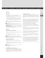
Assembly
Upper Frame, Height and Tilt Adjustment
Note:
The Frame height and seat tilt settings will be factory set to the
standard position unless directed otherwise via customer order. The seat
height and tilt location may be moved to any of three heights and tilts. To
change seat height and tilt, use the following procedure;
To change seat height, loosen the set screw and then remove the 1/2” DIA
bolt located under the frame which connects the Upper Frame to the Lower
Frame. When the 1/2” bolt is removed, you may vary the seat height Be sure
to maintain the original arrangement for shock absorbers. There should be
a 1/2” long shock absorber plus 2 washers positioned below the Lower Side
Rail. There should be a 1” long shock absorber located just below the Upper
Frame, where the 1/2” bolt screws into the Upper Frame.
For a seat height of 15”, use the 5” bolt plus 1” urethane sleeve with no
spacer.
For a seat height of 16”, use the 6” bolt plus 1” urethane sleeve and a 1”
spacer.
For a seat height of 17”, use the 7” bolt plus 1” urethane sleeve and a 2”
spacer.
Use only bolts and spacers provided by XXL-Rehab. The 1/2” bolt must be
threaded into the Upper Frame for a length of at least 1”.
Re-tighten the set screw to ensure the 1/2” bolt will not become loose dur-
ing wheelchair operation.
To change seat tilt, move the 3/8-16 bolt and nut, located in the rear part of
the frame, to one of three possible tilt locations as determined by the three
holes in the rear of the Upper Frame Side Plate. DO NOT OVER TIGHTEN
NUTS. ‘BARELY SNUG’ IS ENOUGH. (Note that it is not possible to obtain
posterior seat tilt at low seat heights (14” or 15” seat height).
Wheel Lock Adjustment
Wheel locks are attached to the seat frame via two ¼ - 20 socket head
bolts. There are locking nuts located on the inside of the seat frame that can
be easily accessed. To adjust the ‘snugness’ of wheel locks, slightly loosen
the socket head bolts, slide the wheel lock assembly forward or rearward
as needed, then re-tighten the socket head bolts. Test the adjustment by
applying the wheel lock to ensure it can be adequately engaged.
Special Note: When seat height is set at high elevations and rear wheels are
located in the most rearward axle location, you may need to reverse-mount
the wheel locks in order for the brake shoe to contact the tire. This can be
done by reverse mounting only the part of the wheel lock that mounts to
the wheelchair frame, therefore allowing the lever and shoe to be located
more rearwardly.
Frame Width Adjustment
To adjust the frame width, you will need a width adjustment kit from XXL-
Rehab. The kit includes 6 spacers needed to establish the new width, a new
width back upholstery, and a new width seat pan.
Remove the backrest from the wheelchair. Remove the old back upholstery.
Knock out the 2 roll pins (located in the cross-bar) used to maintain the
backrest width. Disassemble the 2 halves of the backrest. Install the new
width adjustment sleeve, or remove sleeves as needed. Reassemble the two
halves of the backrest tubes. With the backrest tubes held parallel to one
another, drill-through the new 1/8” roll-pin holes so that you can re-install
the roll-pins.
Remove the seat pan. Disassemble the lower frame by removing the 5 bolts
that maintain the existing chair width. Install the new width adjustment
sleeve, or remove sleeves as needed. Reassemble the two halves of the
frame. Install the new seat pan.
MOTOR VEHICLE USE
WARNING
Identify whether your chair has been manufactured with the Transit Tie-
Down System (TTDS).
If your chair is NOT equipped with the Transit Tie-Down System (TTDS),
this wheelchair DOES NOT meet standards for motor vehicle seating.
If your chair is equipped with the Transit Tie-Down System (TTDS):
1. If possible and feasible, the rider should transfer to the Original Equip-
ment Manufacturer vehicle seat and use the vehicle restraint.
2. Use only Wheelchair Tie Down and Occupant Restraint Systems (WTORS)
which meet the requirements of SAE J2249 Recommended Practice –
Wheelchair Tie Down and Occupant Restraint Systems For Use in Motor
Vehicles. Do not use WTORS designed to rely on the wheelchair structure
to transfer occupant restraint loads to the vehicle.
3. The rider must not weigh more than 270 kg.
4. The wheelchair has been dynamically tested in a forward –facing mode
for a 30 mph frontal impact test. The wheelchair must be forward facing
during transport.
5. In order to reduce the potential of injury to vehicle occupants, wheel-
chair-mounted accessories, such as trays and respiratory equipment
should be removed and secured separately.
6. Postural supports and positioning devices should not be relied on for
occupant restraint.
7. Do not alter or substitute wheelchair frame parts, components or seating.
8. The figures below show the locations of the wheelchair securement
points, front and back.
9. Use only with Wheelchair Tie Down and Occupant Restraint Systems
(WTORS) that have been installed in accordance with the manufacturer’s
instructions and SAE J2249.
Always follow the regulations of your own country.
Front tiedown
Rear tiedown