background image

11  ENTER 

1.  In  OSD  menu  or  selection  interface,  press  these  key  to  make  the 

selection or save settings.   

2.  In  live  full-screen  viewing  mode,  press  this  key  to  view  a  2×  zoom 

image; press it again to return. 

12  Direction Keys 

1.  In Zoom mode, these keys function as normal direction keys. 
2.  In  the  OSD  setup  menu,  the  direction  keys  are  used  to  move  the 

cursor to previous or next fields. To change the value in the selected 
field, press UP / DOWN keys. 

13  DOME 

Press this key to enter Dome Camera Control mode. 

14  ESC 

Press this key to cancel or exit from certain control mode. 

15  MODE   

Press this key to view in full-screen or multiple window modes. 

16  PLAY/STOP   

Press once to start the playback of recorded video. Press again to exit. 

17  FREEZE 

Press this key to freeze the current viewing screen. 

18  SEQ     

Press this key to start automatic sequence display of cameras. 

19  SEARCH 

Press this key to search recorded video by date/time or event. 

20  MENU 

Press this key to enter the OSD setup menu. 
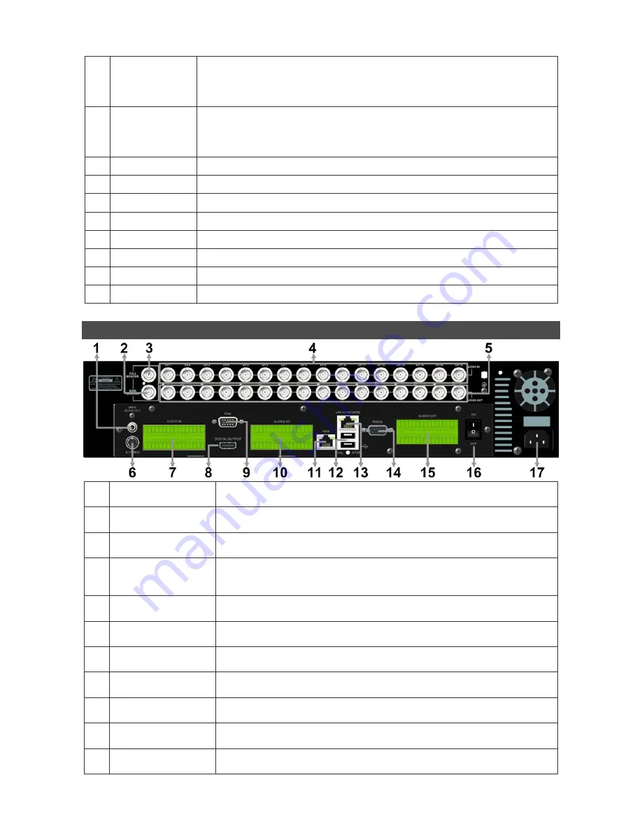
 

Rear Panel 


Main Monitor 
Audio Out 

A  RCA  connector  is  provided  to  output  audio  associated  with  the 
main monitor. 

Main Monitor 
(BNC) 

A BNC connector is provided for connecting to a main monitor. 

Call Monitor 
(BNC) 

A BNC connector is provided for connecting to a call monitor. 

Video In (BNC) 

A  group  of  BNC  connectors  is  offered  for  video  input  streams  from 
installed cameras. The number of connectors equals to the number of 
channels. 

Video Out (BNC) 

The same amount of BNC connectors underneath Video IN (BNC) is 
offered for looping out the video input. 

Main Monitor 
(S-Video) 

An S-Video connector is provided for connecting to a main monitor. 

Audio In   

The  DVR  provides  audio  in  connectors  (a  terminal  block)  for  each 
channel to connect its individual audio source device. 

Main Monitor 
(Digital Output) 

A  digital  output connector  is  provided for  connection  to  a  displaying 
device that transfers data digitally to show the best video quality. 

Main Monitor 
(VGA) 

A  VGA  output  connector  is  offered  for  connecting  to  a  VGA  main 
monitor.   

10 

Alarm I/O & 
RS-485 

The  DVR  provides  alarm  I/O  and  RS-485  ports  that  offer  users  the 
flexibility required to connect the unit to other devices.   

11  NAS Device 

The  NAS  connector  allows  users  to  connect  to  a  Network-Attached 
Storage (NAS) device to expand HDD capacity of the DVR.   

Summary of Contents for XPR16P

Page 1: ...re being recorded 1 In Live and Playback modes press any key to view the corresponding video in full screen 2 In input interface 1 10 can be used for direct input of numbers 0 9 3 In Dome Camera Contr...

Page 2: ...to output audio associated with the main monitor 2 Main Monitor BNC A BNC connector is provided for connecting to a main monitor 3 Call Monitor BNC A BNC connector is provided for connecting to a cal...

Page 3: ...ns for detailed information about monitor functionality Pin Definition of Alarm I O RS 485 4ch Model 8ch Model Pin Definition Pin Definition Pin Definition 1 RS485 D 8 Normal Close B 15 Alarm In 5 8ch...

Page 4: ...VR Check the type of power source before plugging in the power cord to the DVR The acceptable power input is between AC110V AC240V Press the power switch on the rear panel to power on the DVR Select V...

Page 5: ...N keys to select the desired language Network Setup Configure the LAN setup when users plan to use a LAN WAN or Internet connection without a dialup modem It requires an Ethernet connection to a netwo...

Page 6: ...otocols include DSCP Pelco D Pelco P AD422 Fastrax 2 JVC Panasonic_C and Panasonic_N The default is None Note that ID number must match the ID address defined by the dome camera To configure the RS 48...

Page 7: ...s ENTER to select or de select a channel Move the cursor to Event List and press ENTER to list the event video of the selected channels The list displays each event by date time triggered camera and a...

Page 8: ...ck OK to accept the settings and close the Security Settings screen Using the Remote Software Start the IE and enter the IP address of the Premium H 264 DVR in the address bar The ActiveX controls and...

Page 9: ...nstant Recording 9 Setup Menu 2 Smoothen the Image 10 Search Event List 3 Deflicker On Off at Playback 11 Capture Snapshot 4 Audio On Off 12 4 3 Viewing Aspect 5 Select Camera 13 Playback Control 6 Di...

Page 10: ...Open and the file selection screen is displayed Select the drv video file to playback and click OK Click OK to start the playback or click Cancel to abort View the video playback using the Playback co...

Page 11: ...ow will be shown as below on the left Access Connect to device and users can create bookmarks for DVRs or IP cameras via entering hostname IP address port username and password of the devices If a DVR...

Page 12: ...rk 10017 United States E usasales x vision co uk Manufactured exclusively for Xvision www x vision co uk TECHNICAL SUPPORT ForTechnical Support for any Xvision product please contact your local distri...

Reviews: