


4. Startup
&
Shutdown
►
Startup
①
Connect the monitor and the power.
②
The device will boot and the power indicator will display blue.
③
A wizard window will pop up.
►
Shutdown
By IR remote controller
–
Press power button to see a shutdown window. The device will shut down by selecting “OK” button. Then
disconnect the power.
By mouse – Go to “Main Menu” and then select “Shutdown” icon. This will bring up a shutdown window. The device will shut down by
clicking “OK” button. Then disconnect the power.
Descriptions
Name
Audio
In
Audio Out
K/B
Alarm In
Alarm inputs for connecting
sensors
GND
Grounding
Alarm Out
Relay output; connect to external alarm
Connect to keyboard. A is TX+, B is TX-
Audio ouput; connect to the sound box
For two-way talk; connect to active pickups
2
Connect
to high-definition display device
VGA output; connect to monitor
Network port
Connect to USB devices (unavailable
for
upgrade)
Descriptions
Name
VGA port
LAN
HDMI port
USB
Connect to external SATA HDD for backup
E-SATA
P/Z
Connect to speed dome. Y is TX+, Z is TX-
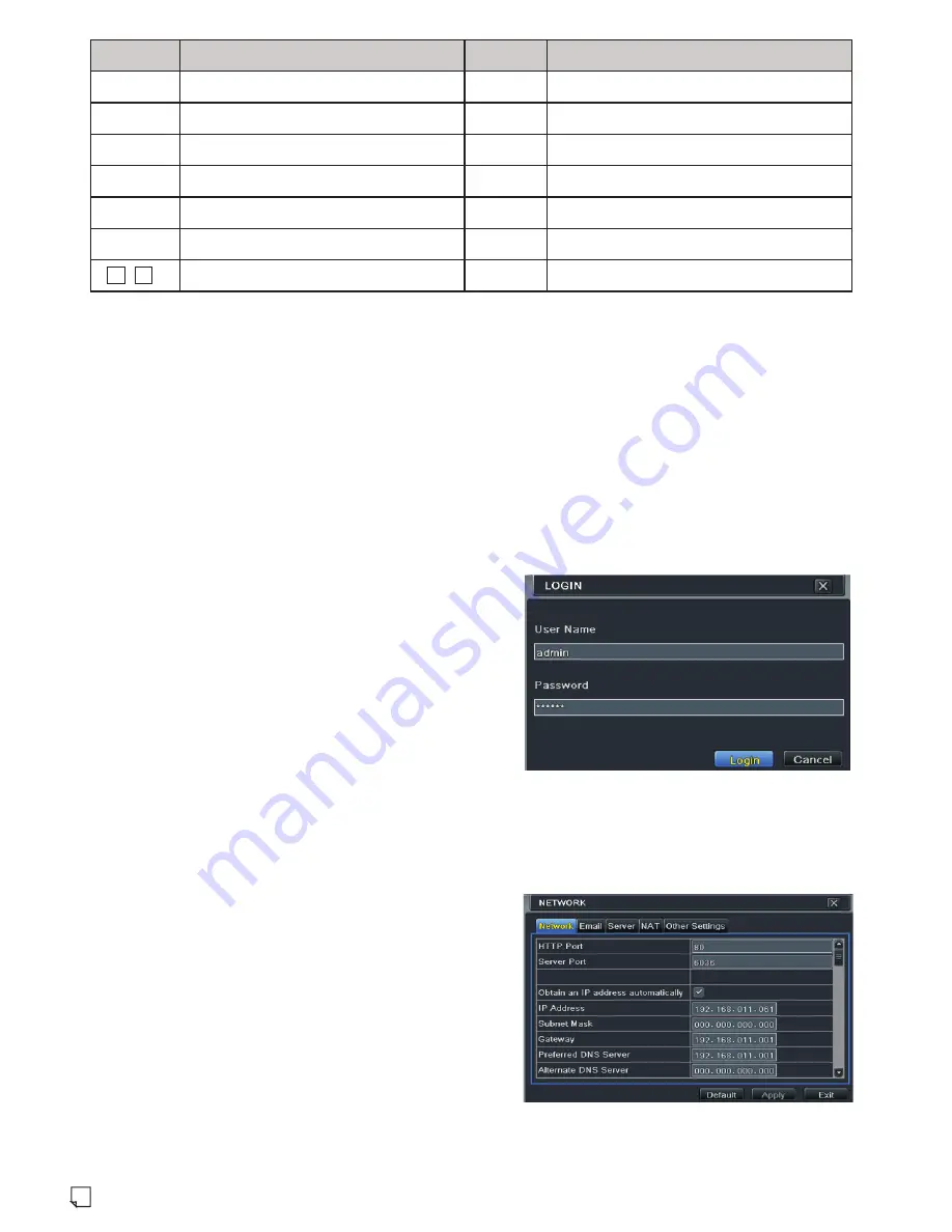
5. Login
After the wizard setup, you can see the live image. Right click to pop
up a menu toolbar. Click “Main Menu” button. This will take you to see
a login box. The default username is
admin
; the
default
password
is
123456
.
Enter username and password and click “Login” button to go
to the main menu setup.
6. Network Configuration
►
LAN
①
Set the network of the NVR. Go to Main Menu
→
Setup
→
Network
→
Network as shown in Fig 1. Input HTTP port (the default value is 80),
server port (the default port is 6036), IP address, subnet, gateway, etc.
If using DHCP, please enable DHCP in both the NVR and the router.
②
Go to Main Menu
→
IP Camera tab as shown in Fig 2. Click “Search”
button to search the IP cameras in the same local network (The IPC
which supports the Onvif protocol may be added manually). If the IPC
is not in the same local network as the NVR, you can select the device
and click “Setup” as in Fig 3 to modify the IP address. Please refer to
the Chapter 4 of NVR User Manual.
After you finish adding IP cameras, you can see the live images through the monitor of the NVR. You may connect the previous 16 CH
directly to the device through IPC direct connection network ports and then add the IP cameras for the remaining channels into the NVR via
WAN/LAN. The following will mainly introduce how to add the IP cameras via LAN/WAN.
(Fig 1)
IPC direct connection network ports
-
1
16


