


19
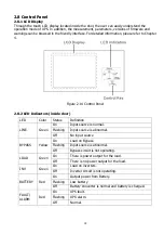
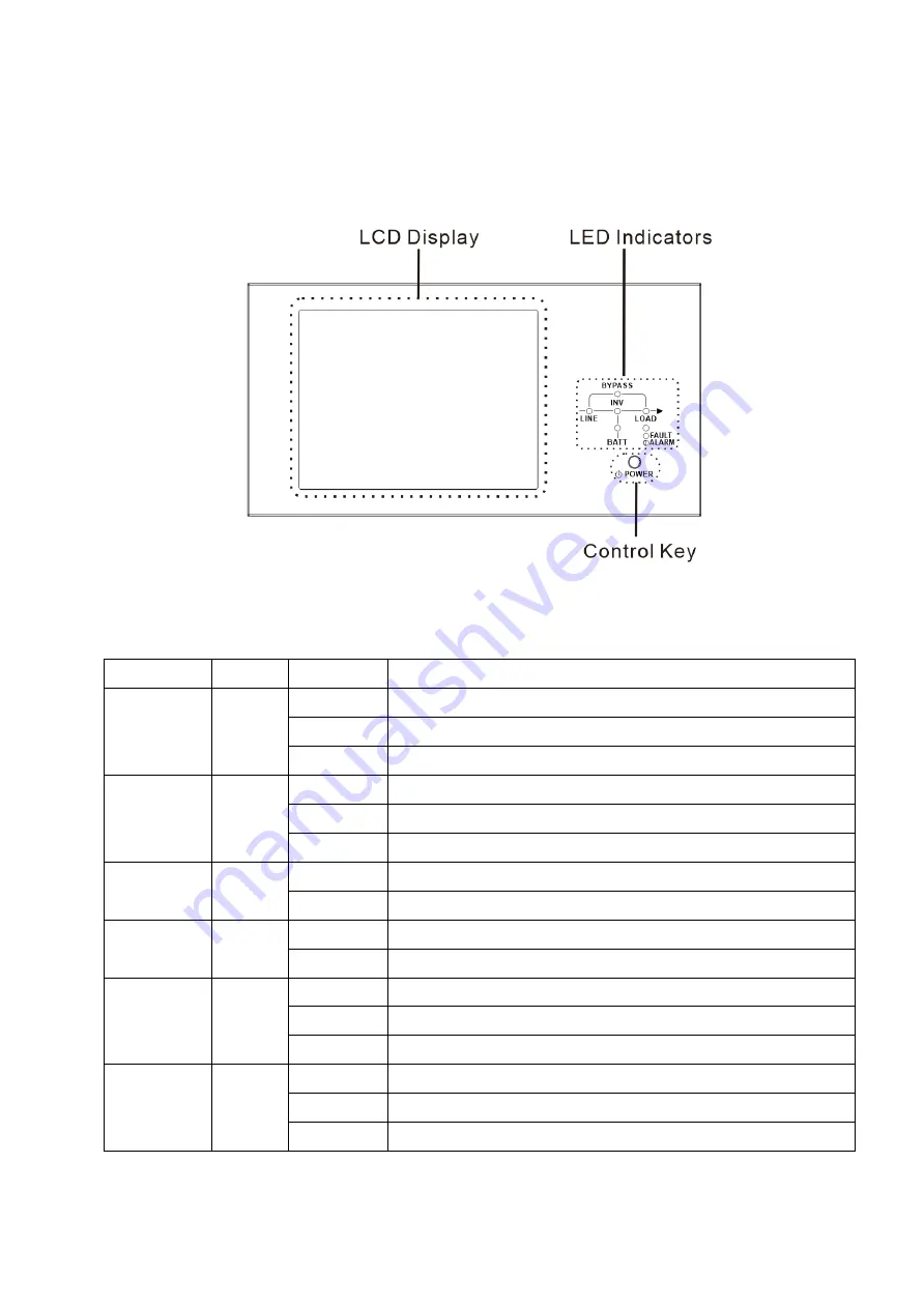
2.8 Control Panel
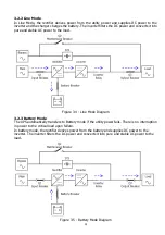
2.8.1 LCD Display
Through the touch LCD display located inside the door, the user can easily understand the
operation mode of UPS. In addition, the measurement, parameters, versions of firmware and
warnings can be browsed in the friendly interface. For detailed information, please refer to Chapter
4.
Figure 2-14 Control Panel
2.8.2 LED Indicators (inside door)
LED
Color
Status
Definition
LINE
Green
On
Input source is normal.
Flashing
Input source is abnormal.
Off
No input source
BYPASS
Yellow
On
Load on Bypass.
Flashing
Input source is abnormal.
Off
Bypass circuit is not operating.
LOAD
Green
On
There is power output for the load.
Off
There is no power output for the load.
INV
Green
On
Load on inverters.
Off
Inverter circuit is not operating.
BATTERY
Red
On
Output power from Battery.
Flashing
Low battery
Off
Battery converter is normal and battery is charged.
FAULT/
ALARM
Red
On
UPS fault.
Flashing
UPS alarm.
Off
Normal.
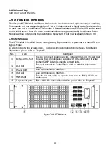
Summary of Contents for X90-5S
Page 17: ...15 X90 ENC5S...
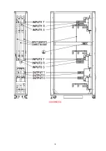
Page 18: ...16 X90 SMB350...
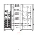
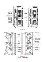
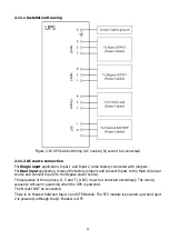
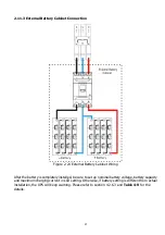
Page 19: ...17 X90 ENC10S X90 SMB700 Figure 2 13 Terminal Blocks...


