background image

10

GB

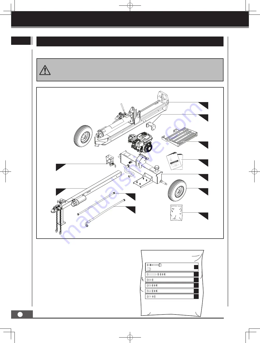
1.   Tank & Engine 

2.  Tongue & Stand

3.  Beam & Cylinder

4.  Wheel/Tire

5.  Beam Lock Bracket

6.  Beam Pivot Bracket

7.  High-Pressure Oil Line Tube

8.  Oil Return Line Tube

9.  Log Catcher Kit

10. Operator’s Manual and Engine Manual

Your log splitter comes partially assembled and contains the following:

CONTENTS SUPPLIED

Heavy lifting required. Some of the components in these assembly instructions are 
heavy and can't be lifted by one person safely. Please plan to assemble this product 
when another person can be available to help.

1

4

7

8

10

11

6

3

5

2

9

11.  Hardware Kit, Including:


×

 2

A


×

 1


M12 

×

 110

×

 2

B


M6 

×

 20

×

 3

C


M12 

×

 35

×

 2

D


M12 

×

 35

×

 4

E


M12 

×

 35

×

 2

F

ASSEMBLY

ASSEMBLY

Summary of Contents for 196CC

Page 1: ...CTIONS FOR QUESTIONS PLEASE CALL CUSTOMER SERVICE 909 628 4900 SAVE THIS MANUAL KEEP THIS MANUAL FOR SAFETY WARNINGS PRECAUTIONS ASSEMBLY OPERATION INSPECTION MAINTENANCE AND CLEANING PROCEDURES WRITE THE PRODUCT S SERIAL NUMBER ON THE BACK OF THE MANUAL OR THE MONTH AND YEAR OF PURCHASE IF PRODUCT HAS NO SERIAL NUMBER ...

Page 2: ...Carefully read through this entire operator s manual before using your new unit Pay attention to all cautions and warnings This unit is a gasoline engine driven hydraulic log splitter It is designed to split wood logs for use as firewood for a stove or fireplace This log splitter will only split logs lengthwise with the grain Engine Manual The Engine Manufacturer is responsible for all engine rela...

Page 3: ...5 Hydraulic Cylinder Stroke 24 Hydraulic Rod Diameter 1 75 2 Cylinder Cycle Time 11 2 seconds 12 9 seconds 12 7 seconds Hydraulic Oil Required to Fill 4 49 Gallon 4 75 Gallon 6 34 Gallon Hydraulic Oil Included Not Included Replacement Filters Built in Filter Beam Heavy duty H shape formed construction Wedge Size 7 8 Wedge Style 2 way Rear Wheels 4 80 8 DOT Approved 16 O D Road Tires Hitch Coupler ...

Page 4: ...ngest portion of the log should be rotated down and the most square end placed toward the end plate Wear protective gloves Wear safety footwear Do not remove or tamper with the protection and safety devices Don t stand or sit on the log splitter Operate the log splitter on level surfaces Stay off slopes and slippery surfaces Do not touch parts that are hot from operation Serious burns may result N...

Page 5: ...el Keep your hair clothing and gloves away from moving parts Loose clothes jewelry or long hair can be caught in moving parts Protect eyes face and head from objects that may be thrown from the unit Always wear safety goggles or safety glasses with side shields when operating Wear appropriate hearing protection Always keep hands and feet away from all moving parts during operation Moving parts can...

Page 6: ...a while adding fuel or operating the unit Never fill the fuel tank indoors Keep grounded conductive objects such as tools away from exposed live electrical parts and connections to avoid sparking or arcing These events could ignite fumes or vapors Always stop the engine and allow it to cool before filling the fuel tank Never remove the cap of the fuel tank or add fuel while the engine is running o...

Page 7: ...he tank could contain hot oil under pressure which could result in serious injury Do not adjust the pressure setting on the hydraulic pump or valve If injured by escaping fluid no matter how small the wound is see a doctor at once A typical injection injury may be a small wound that does not look serious However severe infection or reaction can result if proper medical treatment is not administere...

Page 8: ...he bark side of the logs when loading or positioning never the ends Never place your hands or any part of your body between a log and any part of the log splitter Do not straddle or step over the log splitter during operation Do not reach or bend over the log splitter to pick up a log When stabilizing a log with the left hand remove your hand when the wedge contacts the log or serious injury may o...

Page 9: ...her 5 Use a 13mm wrench or socket to remove the two hex bolts that secure the engine to the crate bottom as shown below 6 Remove Tank Engine Assembly from crate then remove the engine assembly 3 Remove beam and cylinder assembly from metal crate with assistance of a helper Lift beam and cylinder assembly to its vertical position standing upright on the beam s footplate 4 Use a 13mm wrench or socke...

Page 10: ...our log splitter comes partially assembled and contains the following CONTENTS SUPPLIED Heavy lifting required Some of the components in these assembly instructions are heavy and can t be lifted by one person safely Please plan to assemble this product when another person can be available to help 1 4 7 8 10 11 6 3 5 2 9 11 Hardware Kit Including 2 A 1 M12 110 2 B M6 20 3 C M12 35 2 D M12 35 4 E M1...

Page 11: ...ory To assemble your machine follow the below instructions Engine 1 Remove Engine Bolts from tank 2 Place Engine on tank Secure Engine on Tank in 4 places with Hex Bolt M8 45mm Flat Washer M8 and Hex Nut Locking nut M8 ASSEMBLY M8 45 4 M8 45 4 M8 45 4 ASSEMBLY ...

Page 12: ...pindle The slotted nut should be attached with a 28mm socket tight enough to eliminate the free play of the wheel assembly and not tighter Make sure the wheels can freely rotate The Castle Nut needs to be oriented to allow for the installation of the Cotter Pin Install the Cotter Pin through the Castle Nut and spindle Bend pin ends around spindle to secure its position Install the Hub Cap using th...

Page 13: ...Beam To Reservoir 1 Rotate the Stand attached to the side of the Tongue downwards into position by releasing the pin and then securing the release pin 2 Remove the Retaining Clip and Hitch Pin from the assembled unit as shown below Slowly back the assembled unit up to the Beam Cylinder Align the Tongue Bracket of the assembled unit to the Pivot Bracket of the Beam Once the brackets are aligned ins...

Page 14: ...he two hydraulic hoses to the valve pump tank as shown in detail drawing Securely tighten the fitting connections using 27mm and 32 mm wrenches Log Catcher 1 Align holes in log catcher with holes in the beam 2 Secure the log catcher on the beam with the provided M12 35 bolts lock washers and flat washers Suction Line Tube Pump Hose Clamp High Pressure Oil Line Tube Oil Return Line Tube 1 2 M12 x 3...

Page 15: ...B KNOW YOUR MACHINE Features and Controls Manual Canister Lifting Handle Split Control Handle 2 Ball Hitch Coupler Tank Foot Plate Beam Assembly Log Catcher Log Stripper Cylinder Beam Lock Bracket OPERATION ...

Page 16: ... The throttle control moves between FAST SLOW and STOP positions Split Control Handle The control handle is used to move the wedge up and down to split logs The control handle has three positions Forward Neutral and Reverse See the operation section for instruction Manual Canister Keep manuals safely in the canister Beam Lock Bracket The beam lock bracket is used to secure the beam in the horizont...

Page 17: ...roperly when the fuel tank has been filled to the recommended level Overfilling may cause permanent damage to evaporative emissions control system components Filling to the recommended level ensures a vapor gap required to allow for fuel expansion Pay close attention while filling the fuel tank to ensure that the recommended fuel level inside the tank is not exceeded Use a portable gasoline contai...

Page 18: ...ve 4 Move the choke lever to the CLOSED position 6 Pull the recoil starter until engine compression has become difficult to pull Let the recoil return to the home position then pull quickly to start the engine Repeat steps as needed Fully open the choke and set the throttle to the FAST position before operating the unit OPEN CLOSED SLOW FAST ON OFF ON OFF 5 Start the engine and use the control val...

Page 19: ...erse position Move the lever in this position to retract the cylinder Push the lever fully in this direction to lock it return mode The lever will automatically return to the neutral position once the cylinder fully retracts Reverse Position Forward Position Neutral Position Reverse Position Neutral Position Forward Position Keep hands and fingers away from the splitter wedge and log stripper duri...

Page 20: ...en release the lever and make sure the leg is secured 2 Check the tires to ensure they are fully inflated to 30 PSI for proper functionality Towing by vehicle 1 Turn the fuel shut off valve off This prevents fuel from flooding the engine ON OFF TRANSPORTING The log splitter is heavy It can crush and cause serious injury if it rolls out of control or tips over Make sure the log splitter engine is o...

Page 21: ...wer housing rotating screen and muffler areas Use a drain pan to aid in the removal of all used oil and particles 1 Disconnect the suction line tube from the pump by loosing the hose clamp 2 Drain oil from the suction line tube 3 After oil has been completely drained from the machine reattach the suction line tube to the pump Oil Draining MAINTENANCE Turn off the towing vehicle before leaving the ...

Page 22: ...use acid and gum deposits that form in the fuel system or on carburetor parts For engine fuel that is stored less than 30 days add a fuel stabilizer to keep the fuel fresh Turn the fuel valve lever to the off position If fuel is stored over 30 days then drain the fuel tank as stated in the engine manual Always drain fuel from the tank in an outdoor well ventilated area Stay away from sources of he...

Page 23: ...r service 3 Check oil level and add as needed Wedge does not auto return 1 Low hydraulic oil 2 Faulty control valve 1 Check oil level and add as needed 2 Contact customer service Excessive bouncing while towing Underinflated Inflate tires to proper pressure Control valve handle does not return to neutral when released from forward position 1 Hydraulic oil too cold 2 Hydraulic oil too thick 3 Hydra...

Page 24: ...1 12 39 36 35 34 23 47 50 51 52 53 54 55 56 57 58 59 60 64 61 65 49 48 46 28 33 32 31 29 30 45 23 66 40 41 20 68 69 32 68 20 73 75 76 77 79 78 74 72 71 70 67 27 13 7 9 23 42 22 42 23 62 63 80 81 11 10 OPTIONAL 15 19 11 80 81 PARTS INFORMATION ...

Page 25: ...1 40 High Pressure Oil Line Tube 1 No Description Q ty 41 Oil Return Line Tube 1 42 Lock Washer M8 12 43 44 45 Hex Bolt M8 40 4 46 Tank 1 47 Vent Cap 1 48 R Clip 1 49 Hitch Pin 1 50 Hex Bolt M8 20 4 51 Pump 1 52 Key 3 25 1 53 Jaw Coupler Assembly Right 1 54 Flat Washer M4 4 55 Lock Washer M4 4 56 Hex Bolt M4 8 4 57 Pump Cover Cover 1 58 Bolt M6 10 4 59 Spider 1 60 Jaw Coupler Assembly Left 1 61 Ke...

Page 26: ...0 High Pressure Oil Line Tube 1 No Description Q ty 41 Oil Return Line Tube 1 42 Lock Washer M8 12 43 44 45 Hex Bolt M10 45 4 46 Tank 1 47 Vent Cap 1 48 R Clip 1 49 Hitch Pin 1 50 Hex Bolt M8 20 4 51 Pump 1 52 Key 3 25 1 53 Jaw Coupler Assembly Right 1 54 Flat Washer M4 4 55 Lock Washer M4 4 56 Hex Bolt M5 10 4 57 Pump Cover Cover 1 58 Bolt M6 10 4 59 Spider 1 60 Jaw Coupler Assembly Left 1 61 Key...

Page 27: ...27 GB PARTS INFORMATION ...

Page 28: ...QUALIFIED TO MAKE ANY REPAIRS TO THE PRODUCT OR THAT HE OR SHE IS QUALIFIED TO REPLACE ANY PARTS OF THE PRODUCT IN FACT THE MANUFACTURER AND OR DISTRIBUTOR EXPRESSLY STATES THAT ALL REPARIS AND PARTS REPLACEMENTS SHOULD BE UNDERTAKEN BY CERTIFIED AND LICENSED TECHNICIANS AND NOT BY THE BUYER THE BUYER ASSUMES ALL RISK AND LIABILITY ARISING OUT OF HIS OR HER REPAIRS TO THE ORGINAL PRODUCT OR REPLAC...

Reviews: