Xtreme Power Systems XtremeLink Installation And Usage Manual Download Page 13


13 

SET HOPPING MODE 
 
Range: 1 to 5 

 
With the STATUS LED solid green, press and hold the PROG button until the 
STATUS  LED  turns  off.    The  STATUS  LED  will  now  slowly  flash  green  the 
number of times equal to the current hopping mode setting.  For example, if 
hopping  mode  is  currently  set  to  3,  the  STATUS  LED  will  flash  green  three 
times. 
 
After the flashing stops you have five seconds to change the hopping mode.  
To  change  the  hopping  mode,  press  and  release  the  PROG  button  as  many 
times as necessary to equal the hopping mode you would like.  For example, 
if  you  wanted  the  hopping  mode  to  be  3,  you  would  press  and  release  the 
button three times. 
 
If you do not press the PROG button within five seconds, or if the value you 
enter exceeds what is allowed, the STATUS LED will alternately flash red and 
green (error condition occurred) and no change will be made.  At this point, 
you  are  back  at  the  programming  mode  start  (where  you  can  select  a 
programming option). 
 
If  you  do  make  a  change,  the  STATUS  LED  will  blink  green/red/orange  in 
rapid succession to let you know that the change was successful. 
 
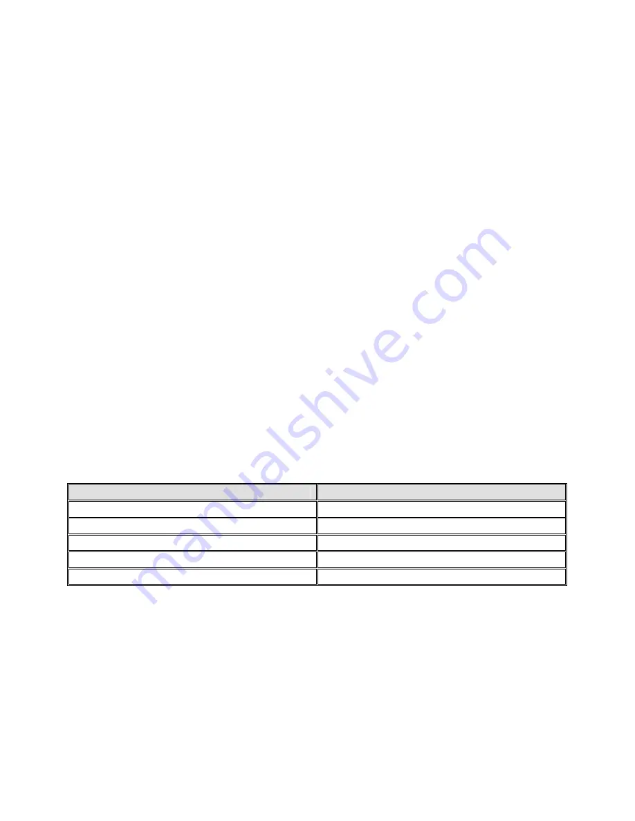
Below is a table of available hopping modes.  
 

Hopping Mode 

Setting 

Single frequency w/predictive 

FCC Full Time 

FCC Full Time w/adaptive 

ETSI Full Time 

ETSI Full Time w/adaptive 


The difference between the FCC and ETSI hopping schemes is the number of 
frequencies  used.    Until  this  product  is  re-certified  to  use  more  frequencies 
(like  what  has  already  been  done  with  ETSI  testing  in  Europe),  the 
frequencies for the U.S. and other FCC compliant countries are same as the 
Single  frequency  w/predictive  hopping  mode.    ETSI  hopping  increases  the 
number of frequencies used in hopping sequence. 
 
Note: adaptive mode is still in development and subject to change.   


Summary of Contents for XtremeLink

Page 1: ... January 11 2011 All material including but not limited to photographs text and concepts contained in this manual is copyright 2006 2011 By Xtreme Power Systems Distribution of this data without permission is strictly prohibited All rights reserved worldwide DUE TO FREQUENT CHANGES IN THIS MANUAL PLEASE DO NOT POST UPLOAD OR OTHERWISE PROVIDE THIS INFORMATION VIA ANY MEANS ...

Page 2: ...a limited lifetime warranty Units subject to improper installation misuse abuse or modifications will not be covered under this warranty Xtreme Power Systems may at its discretion either repair or replace the unit covered under warranty The customer will pay all freight charges to and from Xtreme Power Systems Xtreme Power Systems must be contacted to obtain a return authorization Any product retu...

Page 3: ...3 NOTICE THIS SYSTEM REQUIRES PROPER POWER PLEASE READ SECTION 5 FOR INFORMATION ON THE RECOMMENDED POWER SETUP AND HOW TO IDENTIFY IF YOU ARE HAVING A POWER PROBLEM ...

Page 4: ...les have tabs either on each side or top and bottom Carefully squeeze these tabs and pull the RF module from the transmitter Sometimes each side or each end will need to be wiggled for the module to come loose and removed See Figures 1 and 2 for reference Figure 1 Futaba RF module removal ...

Page 5: ...5 Figure 2 JR RF module removal ...

Page 6: ...y unscrew If your transmitter has a pivot ball on top that the antenna normally screws into do not screw in the antenna when the XtremeLink RF module is installed If you switch back to a stock RF module remember to re install the antenna or damage may result to the transmitter When using the XtremeLink RF module the transmitter s modulation output must be set to PPM MPLX PPM18 or PPM24 PCM APCM SP...

Page 7: ...7 Figure 3 Futaba XtremeLink module installation ...

Page 8: ...8 Figure 4 JR XtremeLink module installation ...

Page 9: ... to show it off Mount the receiver as high and out in the open as possible so you can easily see it and get access to it see Figures 5 6 for examples Under no circumstance can you wrap or pass servo wires around the antenna Remember that wires can move under g force so make sure that wires can not move at all around the receiver Moving wires can cause intermittent radio control See figures 5 and 6...

Page 10: ...iver will power up and appear to work but it will not function properly powered this way Power and ground are available on every numbered slot Signal is the pin nearest the number The function for each channel is determined by the transmitter in use and not the receiver itself For example throttle control with most JR radios is on channel 1 while throttle control on most Futaba radios is on channe...

Page 11: ...Link receiver that has been bound to the XtremeLink RF module must be turned off prior to powering on the transmitter To enter advanced programming mode press and hold the PROG button and then turn on the power to the transmitter Hold the button until the STATUS LED changes from off to green and then finally to red This process will take approximately 7 seconds Once you are in programming mode eac...

Page 12: ...ess and release the PROG button just once If you wanted the power level to be 3 you would press and release the button three times If you do not press the PROG button within five seconds or if the value you enter exceeds what is allowed the STATUS LED will alternately flash red and green error condition occurred and no change will be made At this point you are back at the programming mode start wh...

Page 13: ...ately flash red and green error condition occurred and no change will be made At this point you are back at the programming mode start where you can select a programming option If you do make a change the STATUS LED will blink green red orange in rapid succession to let you know that the change was successful Below is a table of available hopping modes Hopping Mode Setting Single frequency w predi...

Page 14: ...mming mode press and hold the programming button on the XtremeLink receiver until the STATUS LED changes from off to green and then finally red This process will take approximately 7 seconds NOTE The receiver s programming button is located on the circuit board itself and can be depressed using our radio tool available from our online store or by using a 3 32 Allen key or similar BLUNT object DO N...

Page 15: ... Red 1 Set Channel Map Solid Green 2 Set Country Solid Orange 3 Not Used Blinking Red 4 Set Failsafe Map Blinking Green 5 Set Failsafe Time Blinking Orange 6 Telemetry Setup Figure 7 XtremeLink receiver programming button location ...

Page 16: ...ce followed by a one second pause Every time you press and release the programming button the channel map position will advance by one The channel map position begins at output 1 one flash and ends with the number of channels that your receiver has So the 8 channel XtremeLink has eight possible channel map positions while the 10 channel XtremeLink receiver has ten possible channel map positions To...

Page 17: ...y setting For example the default country level is 1 so the STATUS LED will flash just once After the flashing stops you have five seconds to change the country To change the country press and release the programming button the number of times necessary to equal the country from the list below For example if you wanted to set the country to France you would press and release the programming button...

Page 18: ...ilsafe control for each channel output individually You can set each channel to either hold last position or to use the user defined position discussed in section 4 NOTE The default for ALL outputs is hold last position With the STATUS LED blinking red press and hold the programming button until the STATUS LED turns off The STATUS LED will now flash orange the number of times equal to the current ...

Page 19: ...ve seconds or if the value you enter exceeds what is allowed the STATUS LED will alternately flash red and green error condition occurred and no change will be made At this point you are back at the failsafe map position where you can advance to the next channel There is no way to get back to the programming mode start with this feature other than by powering off the receiver and re entering the a...

Page 20: ...5 seconds or if the value you enter exceeds what is allowed the LED will alternately flash red and green error condition occurred and no change will be made At this point you are back at the programming mode start If you do make a change the LED will blink green red orange in rapid succession to let you know that the change was successful FUNCTION 6 TELEMETRY SETUP With the STATUS LED flashing ora...

Page 21: ...er s in binding mode BEFORE putting the transmitter in binding mode Starting with firmware version 3 0 you can have as many slave receivers and a single master receiver bound together If you are not using slave receivers please skip the Slave Receiver binding information below and start with the Master Receiver section Binding the XtremeLink System Slave Receiver s Power on your XtremeLink receive...

Page 22: ...release the button Once the button has been released the units should bind All STATUS LEDs will turn green when a successful bind has occurred If any STATUS LED does not turn green repeat the binding procedure YOU MUST power off your transmitter and receiver s after binding Your XtremeLink system is now ready for use NOTES The XtremeLink receiver s STATUS LED will be green during normal operation ...

Page 23: ...e used 2 Turn on the radio system so servo movement can be observed 3 Using flat ground pavement low cut grass or dirt place the R C device so that the receiver antenna is no less than 6 from the ground This might require you elevating the R C device during the testing 4 Hold your transmitter waist high away from your body 5 Press and hold the PROG button on the transmitter module 6 Walk to a dist...

Page 24: ...n The STATUS LED will begin alternately flashing red and green for about 8 seconds During this time move your sticks and switches to the where you would like them during a failsafe condition NOTE Only those channels programmed in the failsafe map will change to a user defined position All other channels will hold their last positions when a failsafe occurs Servo Outputs The 8 and 10 channel receiv...

Page 25: ...ire at least 3 5 volts or they will reboot By comparison non computerized receivers will work on just fractions of a volt and never reboot Recommend Power Setups for XtremeLink Receivers 4 cell packs 4 cell packs will work fine with XtremeLink receivers providing you have adequate capacity The rule that we use is no less than 350mAh for each analog servo and no less than 500mAh for each digital se...

Page 26: ...awing excessive current is by unplugging all of the servos from the XtremeLink receiver power on the system so the STAUS LED is green and then plug each servo into the XtremeLink receiver one by one observing the STATUS LED If the STATUS LED doesn t turn solid orange until you start moving the controls then your input voltage is not adequate Please remember that wall chargers included with most ra...

Page 27: ...put voltages with heat or load BECs built into Electronic Speed Controllers ESCs must have enough current capacity to properly power the XtremeLink receiver We have seen many controllers that will not work These are easy to spot as the XtremeLink receiver s STATUS LED will immediately turn solid orange or in worst case conditions cause the receiver to reboot over and over again Although switches m...

Page 28: ... receiver s servo connection bus For example when using an XtremeLink 10 channel receiver power should be connected to the B T port and channel 10 even if a Y cable is required Using two separate flight packs on each end of the servo bus will give you double the current capacity and a functioning system if one pack were to fail PLEASE NOTE THAT THE 6 CHANNEL PARK FLYER RECEIVERS DO NOT HAVE A LOW ...

Page 29: ...y interference received including interference that may cause undesired operation WARNING To satisfy FCC RF exposure requirements for mobile transmitting devices a separation distance of 20 cm or more should be maintained between the antenna of this device and persons during device operation To ensure compliance operations at closer than this distance is not recommended The antenna used for this t...

Reviews: