


Xtreme Power Conversion Corporation
M90S Service Manual
Page 7
Uninterruptible Power Supply
3. Functional block
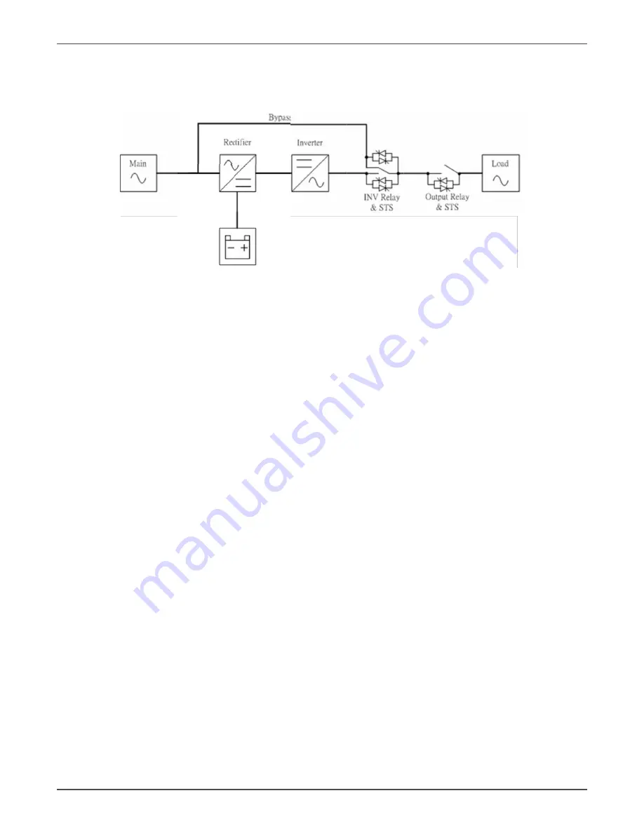
As a true online UPS, the product employs a double conversion topology, comprise following functional
blocks, as shown in Figure 3.1.
Figure 3.1 function block diagram
The CNTL block controls the action of the UPS system, the CNTL also provi des the communication
interface for receiving and executing command from user via the panel or other communication
protocol. When the UPS becomes abnormal, in most case, the CNTL can provide basic information
indicating the status of the UPS.
The Rectifier and PFC blocks are the input stage of the UPS, The blocks converts the AC input power
into two stable DC power storing on the BUS capacitor. In the mean time, PFC(Power Factor Correction)
is performed, the input current tracking the input voltage waveform, and the input power factor can be
corrected to 1, achieving maximum efficiency and producing the lowest power pollution to the utility.
The PFC block in battery mode, called also Booster, is used to convert the low voltage DC power into
higher voltage and more stable DC power, storing on the BUS capacitor also.
The Inverter block is the output stage of the UPS, used to convert the DC power from the BUS
capacitor into sine waveform output power.
When the utility is within the tolerance range, the UPS uses the utility input, at this time, the Rectifier
and PFC work; In case the utility is outside the tolerance range, due to either the voltage or the
frequency, the UPS will stop the Rectifier and PFC working, start the Battery Booster. In case the input
utility interrupts suddenly, the controller can detect the interruption in very short time, and in the
interval before detecting the interruption, the output power will be maintained by energy stored in the
BUS capacitor, there will never be interruption on output. The charger charges the battery when the
utility is normal. The charger converts the AC input power intoDC power for recharging the battery.
The Input or Output EMI section provides EMI filter function. This section can prevent the UPS from
being interfered by external electronic/magnetic noise generated by the other electronic systems, and
it can prevent the noise generated inside the UPS system from interfering other systems too.
The SPS generates DC power supply needed by operation of the circuit of the UPS itself.
The Bypass provides a path that utility can power the output directly when the Inverter doesn’t work.


