background image

WORK PREPARATION AND USE
When using tool, basic safety precautions should always be 

followed to reduce the risk of personal injury and damage to 

equipment. Read all instructions before using this tool!

1. When attaching the burnishing wheel to your angle grinder, disconnect a corded one from

the power source.

2. Always disconnect the wheel from your angle grinder when cleaning or inspecting it.

3. Do not use in wet or damp locations.

4. Wear eye and hand protection when using and cleaning the wheel.

5. Wear a dust mask when operating.

6. Keep fingers and limbs away from the wheel when it is attached to your grinder.

7. Like any renovating drum,it can cause injury if not properly handle.

8. As with any power tool, the machine should be kept out of the reach of children.

9. Always adhere to all warnings and safety precautions provided with the angle grinder that

this attachment is to be used with.

WARNING: Some dust created by power burnishing, as well as contents from the machine 

may contain chemicals known to cause cancer, birth defects or other reproduction harm and 

can be hazardous to your health.

Assembly

The burnishing attachment is applied with M14-thread angle grinder, 48mm-diameter clamp 

of metal shroud and no load speed less than 4000rpm. Please ensure that the power is cut off 

and unplug the machine before the installation of this burnishing attachment.

Step One: 

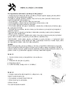
1. Choose the ring that is compatible with your angle grinder.

2. Place it to the right position.

a)

Shroud locator

b)

Optional rings (possible 0-6 rings)

b

a

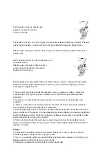
Step


two

:

1.

Press Spindle lock button(b) to make sure the stability

of the spindle.

2.

Assemble the Driving Wheel(a)onto the spindle.

3.

Fix the Driving Wheel(a) tightly.

a)

Driving Wheel

b)

Spindle Lock button

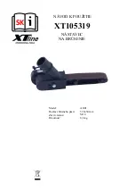
Summary of Contents for XT105319

Page 1: ...CZ N VOD K POU IT XT105319 N STAVEC NA BROU EN Model Rozm r brusn ho p su Z vit v etene Hmotnost AG01 533x30 mm M14 0 6 kg...

Page 2: ...m a dodr ujte v echna varov n a bezpe nostn pokyny dodan spolu s hlovou bruskou ke kter je tento n stavec zkonstruov n VAROV N Ur it druhy prachu uvol uj c se b hem le t n a z ur it ch st samotn ho za...

Page 3: ...hn te roub j Kryt p su Krok 8 1 P i roubujte dr adlo k na n stavec k Dr adlo Krok 3 1 Namontujte brusn n stavec c na hlovou brusku 2 Nasa te obj mku n stavce na reduk n krou ek tak aby po cel m obvod...

Page 4: ...e doj t k zaseknut p su nebo jeho p etr en 6 V dy vyb rejte vhodn brous c p s pro dan pracovn kon Neprov d jte brusn kony na materi lech kter k tomu nejsou vhodn M e doj t k po kozen materi l i dokon...

Page 5: ...rodejn dokumenty podrobn popis z vady a kontaktn daje zp te n adresa telefon Vady kter lze odstranit budou opraveny v z konn lh t 30 dn dobu lze po vz jemn dohod prodlou it Po projeven skryt vady mate...

Page 6: ...SK N VOD K POU ITIE XT105319 N STAVEC NA BR SENIE Model Rozmer br sneho p su Z vit vretena Hmotnos AG01 533x30 mm M14 0 6 kg...

Page 7: ...e na vedomie a dodr iavajte v etky varovania a bezpe nostn pokyny dodan spolu s uhlovou br skou ku ktorej je tento n stavec skon truovan VAROVANIE Ur it druhy prachu uvo uj ce sa po as le tenie a z ni...

Page 8: ...sp do polohy vpravo rovnako ako v smere pky na obr zku Krok 7 1 Umiestnite kryt p su j do dr ky a dotiahnite skrutku j Kryt p su Krok 8 1 Priskrutkujte dr adlo k na n stavec k Dr adlo Krok 3 1 Namontu...

Page 9: ...s k zaseknutiu p su alebo jeho pretrhnutie 6 V dy vyberajte vhodn br siaci p s pre dan pracovn kon Nevykon vajte brus kony na materi loch ktor na to nie s vhodn M e d js k po kodeniu materi lov i doko...

Page 10: ...edajn dokumenty podrobn popis z vady a kontaktn daje spiato n adresa telef n Chyby ktor mo no odstr ni bud opraven v z konnej lehote 30 dn dobu m u po vz jomnej dohode pred i Po prejavenie skryt chyby...

Page 11: ...PL INSTRUKCIA OBSLUGI XT105319 URZ DZENIE DO SZLIFOWANIA Model Rozmiar ta my szlifierskiej Gwint wrzeciona Waga AG01 533x30 mm M14 0 6 kg...

Page 12: ...e e i rodk w ostro no ci do czonych do szlifierki k towej z kt r ma by u ywana ta nasadka OSTRZE ENIE Niekt re py y powsta e w wyniku wypalania a tak e zawarto maszyny mog zawiera chemikalia o kt rych...

Page 13: ...s b jak pokazano na rysunku Krok 7 1 Za o y os on paska j na p k i zacisn wkr t j Os ona paska Krok 8 1 Przykr uchwyt k do nasadki k Uchwyt Krok 3 1 Umie ko c wk do szlifowania c na szlifierce k towej...

Page 14: ...ie a nawet p kni cie 6 Zawsze wybieraj odpowiedni pasek do odpowiednich materia w Nie szlifuj materia w kt re nie s zalecane gdy mo e to spowodowa uszkodzenie narz dzi a nawet zranienie Konserwacja 1...

Page 15: ...GB USER MANUALL XT105319 GRINDING ATTACHMENT Model Sanding belt size Clamping Weight AG01 533x30 mm M14 0 6 kg...

Page 16: ...9 Always adhere to all warnings and safety precautions provided with the angle grinder that this attachment is to be used with WARNING Some dust created by power burnishing as well as contents from t...

Page 17: ...as the direction shown in the picture Step seven 1 Position the belt cover j onto the shelf and tighten up the screw j Belt cover Step eight 1 Screw the handle k onto the attachment k handle Step thr...

Page 18: ...eak 6 Always choose the right belt for proper materials Do not sanding on the materials that is not recommended which wil l damage the tools and even get yourself hurt Maintenance 1 Before each use cl...

Reviews: