background image

CUSTOMER SERVICE 1-888-707-1880                              Maurice Pincoffs Canada

©

2012


10

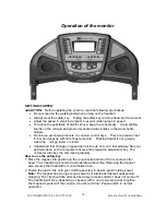
Operation of the monitor 


GETTING STARTED: 

CAUTION:  

Before operating the console, read the following precautions: 

  Do not stand on the walking belt when turning on the treadmill 

  Always wear the safety key.    Pulling the safety key will stop tread-belt movement. 

  Adjust the speed in small increments to avoid sudden jumps in speed 

  To reduce the possibility of electric shock, keep the console dry.    Avoid spilling 

liquids on the console and place only sealed water bottles in the water bottle 
holders. 

  Do not use excessive pressure on console control keys.    They are precision set 

to function properly with little finger pressure.    Pushing harder is not going to 
make the  unit go faster or slower.   

  Understand that changes in speed and incline do not occur immediately. Set your 

desired speed on the computer console and release the adjustment key. The 
computer will obey the command gradually. 

How to use the safety key 

1. Place the magnet into position on the round metal portion of the console control 

head. Your treadmill will not start and operate without this. Removing the magnet 
also secures the treadmill from unauthorized use. 

2. Fasten the plastic clip onto your clothing securely to assure good holding power. 

Note: 

The magnet has strong enough power to minimize accidental, unexpected 

stopping. The clip should be attached securely to make certain it does not come off.   
The treadmill will stop, depending on speed, with a one to two step coast anytime 
the magnet is pulled off the console. Use the red Stop / Pause switch in normal 
operation. 

Summary of Contents for 1640855

Page 1: ...Retain For Future Reference Owner s Manual Model No 1640855 Assembly Operation Adjustments Parts Warranty CAUTION Read and understand this manual before operating unit ...

Page 2: ...tant Safety Instructions 2 Before you begin 4 Hardware list 5 Assembly instructions 6 Treadmill operation 9 Operation of the monitor 10 Folding Instructions 14 Part list 15 Parts diagram 19 Belt adjustment 20 General Maintenance 22 Service check list 25 Manufacturer s Limited Warranty 26 ...

Page 3: ...t heavy gauge 14 gauge or better extension cord with a three prong grounded plug and receptacle 4 Never leave the treadmill unattended when plugged in Remove the safety key and unplug the unit from the outlet when not in use and before removing or replacing parts 5 Never operate the treadmill if it has a damaged cord or plug if it is not working properly if it has been dropped damaged or exposed t...

Page 4: ...increase and decrease and will help prevent straining muscles 23 Never hold your breath while exercising Breathing should remain at a normal rate in conjunction with the level of exercise being performed 24 Start your program slowly and very gradually increase your speed and distance 25 Always wear suitable clothing and footwear while exercising Do not wear loose fitting clothing that could become...

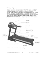
Page 5: ...not be applicable to products being subjected to professional use or products being used in a gym center This exercise equipment was designed and built for optimum safety However certain precautions apply whenever you operate a piece of exercise equipment Be sure to read the entire manual before assembly and operation of this machine Before reading further please familiarize yourself with the part...

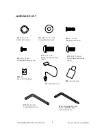
Page 6: ...ng Screw 4pcs 94 Ø5 16 19 1 5T Curved Washer 2pcs 132 M5 Speed Nut Clip 4pcs 93 5 16 15m m Button Head Socket Bolt 8pcs 33 Safety Key 1pc 90 5 16 3 4 Button Head Socket Bolt 4pcs 95 M5 10m m Phillips Head Screw 2pcs 58 Lubricant 1pc 97 M6 66 86 L Allen Wrench 1pc 96 Combination M5 Allen Wrench Phillips Head Screw Driver 1pc ...

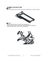
Page 7: ...move all the parts from the carton and lay the main base frame on a flat level surface STEP 2 Slide the right frame base cover 42 on the right upright 4 Connect the lower computer cable 39 to the computer extension cable 38 Slide the left frame base cover 43 on the left upright 5 39 38 42 43 4 5 ...

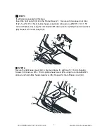
Page 8: ... and one Ø5 16 19 1 5T Curved Washer 94 using the combination M5 allen wrench phillips head screwdriver 96 Repeat for the left upright 5 94 93 93 94 93 93 5 4 96 132 132 132 132 STEP 4 Secure the right base cover 42 to the main frame 1 with two 5 16m m Tapping Screws 88 and one M5 10m m phillips head screw 95 using the combination M5 allen wrench phillips head screwdriver 96 Repeat for the left ba...

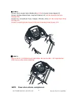
Page 9: ...th the Speed Hand Pulse Complex 53 Connect the Incline Hand Pulse Complex W Cable 128 with the Incline Hand Pulse Complex 54 Connect Connecting Cable Upper 152 and Connecting Cable Lower 131 38 37 127 128 54 53 152 131 STEP 6 Use four 5 16 3 4 Button Head Socket Bolts 90 and four Ø8 1 5T Split Washers 148 to secure the console assembly 148 90 148 90 NOTE Ensure that all bolts are tightened ...

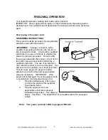
Page 10: ...ther the product is properly grounded Do not modify the plug provided with the product if it will not fit the outlet have a proper outlet installed by a qualified electrician The use of an extension cord with this product is not recommended If an extension cord is needed use a short less than 10 feet heavy gauge 14 gauge or better extension cord with a three prong grounded plug and receptacle IMPO...

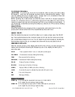
Page 11: ...er is not going to make the unit go faster or slower Understand that changes in speed and incline do not occur immediately Set your desired speed on the computer console and release the adjustment key The computer will obey the command gradually How to use the safety key 1 Place the magnet into position on the round metal portion of the console control head Your treadmill will not start and operat...

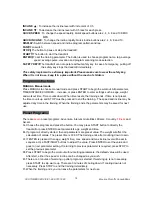
Page 12: ...ey is in place simply press the START key The treadmill will start at the minimum speed of 0 5 mph the time will count up from zero and all data will begin to accrue You can adjust the speed manually by pressing the Fast and Slow buttons and you can adjust the Incline with the Up and Down buttons WINDOW DISPLAYS After the console powers on the display will show the Time When you start a program th...

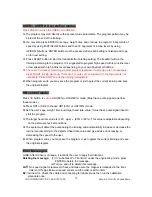
Page 13: ...resets the training ends If time is not preset the time counts up and STOP must be pressed to end the training The speed and incline may be adjusted any time in the training When the training ends the parameters may be saved for next use Preset Programs There are seven preset programs Adventure Interval Glute Blast Xtreme Xcountry Fitness and Ascent A Choose the program and press the button You ma...

Page 14: ...st neglect the current training and save the original program HR control mode Press HR button to switch HR1 60 or HR2 80 mode Must have pulse signal to perform these modes A Press HR1 or HR2 to choose HR1 60 or HR2 80 mode B Set the user s age weight time and target heart rate value It must have pulse signal input to start the program C The target heart rate value is 220 age 60 or 80 This value is...

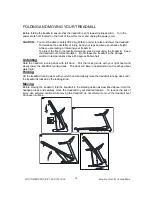
Page 15: ...ll out of direct sunlight Do not leave the treadmill in the storage position in temperatures above 85 degrees Fahrenheit Unfolding Hold the treadmill running deck with left hand Pull the locking knob with your right hand and slowly lower the treadmill running deck The deck will lower unassisted when it reaches about waist high Folding Lift the treadmill running deck with your left hand and slowly ...

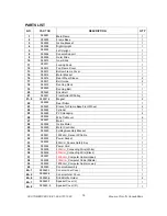
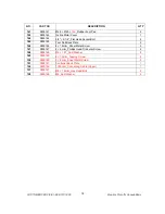
Page 16: ...net 2 22 085522 Rear Roller 1 23 085523 Sleeve for Frame Base Front Wheel 2 24 085524 Cylinder 1 25 085525 PVC Handgrip 2 26 085526 Wire Tie Mount 6 27 085527 Motor 1 28 085528 Incline Motor 1 29 085529 Motor Controller 1 30 085530 Folding Assembly Bracket 1 31 085531 1000m m_Sensor W Cable 1 32 085532 Power Socket 1 33 085533 800m m_Square Safety Key 1 34 085534 Power Cord 1 35 085535 300m m_Conn...

Page 17: ...Cap 2 42 085542 Frame Base Cover R 1 43 085543 Frame Base Cover L 1 44 085544 Frame Base Front Wheel 2 45 085545 Frame Base Rear Wheel 2 46 085546 30 60m m_Square End Cap 2 47 085547 Motor Cover Anchor 5 48 085548 Motor Top Cover 1 49 085549 1420m m_Foot Rail 2 50 085550 Cushion 6 51 085551 Rear Adjustment Base L 1 52 085552 Rear Adjustment Base R 1 53 085553 Speed Hand Pulse Complex 1 54 085554 I...

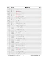
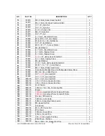
Page 18: ...4 085594 Ø5 16 19 1 5T_Curved Washer 2 95 085595 M5 10m m_Phillips Head Screw 6 96 085596 Combination M5 Allen Wrench Phillips Head Screw Driver 1 97 085597 M6 66 86 _L Allen Wrench 1 98 085598 3 8 1 1 2 _Hex Head Bolt 1 99 085599 3 8 1 1 2 _Hex Head Bolt 1 100 0855100 3 8 1 3 4 _Hex Head Bolt 1 104 0855104 21 4 21 4m m_Square End Cap 1 105 0855105 25 4 25 4m m_Square End Cap 1 123 0855123 On Off ...

Page 19: ...ad Socket Bolt 2 145 0855145 Foot Rail Back Plate 2 146 0855146 4 19m m_Sheet Metal Screw 2 147 0855147 4 6m m_Phillips Head Trilobular Screw 2 148 0855148 Ø8 1 5T_Split Washer 4 149 0855149 5 19m m_Tapping Screw 5 150 0855150 3 8m m_Sheet Metal Screw 2 151 0855151 Controller Back Plate 1 152 0855152 1000m m_Connecting Cable Upper 1 157 0855157 M8 12m m_Hex Head Bolt 2 158 0855158 M8_Split Washer ...

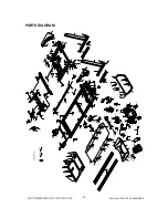
Page 20: ...CUSTOMER SERVICE 1 888 707 1880 Maurice Pincoffs Canada 2012 19 PARTS DIAGRAM ...

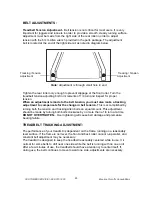
Page 21: ... in belt tension This is accomplished by turning both the tension and tracking Allen bolts an equal amount This adjustment should be made by turning both bolts clockwise by no more than a 1 4 turn at a time DO NOT OVERTIGHTEN Over tightening will cause belt damage and premature bearing failure TREADBELT TRACKING ADJUSTMENT The performance of your treadmill is dependent on the frame running on a re...

Page 22: ...commended intervals ensures the longest life possible for your treadmill If the lubricant dries out the friction between the belt and deck rises and places undue stress on the drive motor drive belt and electronic motor control board which could result in catastrophic failure of these expensive components Failure to lubricate the deck at regular intervals may void the warranty The deck comes pre l...

Page 23: ...ould be done once a month to extend belt and bed life Use water only no cleaners or abrasives A mild soap and water solution along with a nylon scrub brush will clean the top of the textured belt Allow to dry before using Belt Dust This occurs during normal break in or until the belt stabilizes Wiping excess off with a damp cloth will minimize buildup General Cleaning Dirt dust and pet hair can bl...

Page 24: ...reset switch in until it snaps back into place If the reset switch continues to trip see treadbelt adjustment and treadbelt lubrication SPEED SENSOR ADJUSTMENT If the monitor does not display speed or distance the speed sensor and magnet may be misaligned Note Always unplug your treadmill prior to cleaning in order to avoid electrical hazard or shock Follow these steps to check and realign Remove ...

Page 25: ...The large display window will now be showing the Roller size Roller size is used for the calibration process and should be set to 63 To run the calibration procedure press the Start key o The display will show a number for the lowest speed setting for miles the number should be 0 5 Adjust the low speed setting with the Fast Slow keys and press Enter o The display will show a number for the top spe...

Page 26: ...center to the side opposite from the belt movement See General Maintenance section on Treadmill belt Tension Adjust as necessary Motor is not responsive Display is lit Make certain clock is running If it is then service may be Needed Treadmill will only achieve approximately 7 mph but shows higher speed on display This indicates motor should be receiving power to operate Low AC voltage to treadmil...

Page 27: ...ercial or other income producing purpose or 2 subject to misuse neglect accident or unauthorized repairs and alterations This warranty provided herein is in lieu of all other express warranties Any implied warranties including any implied warranties of merchantability or fitness for particular purpose are limited in duration to the first 12 months from the date of purchase All other obligations or...

Reviews: