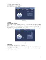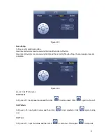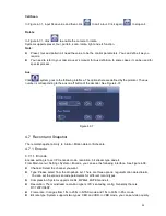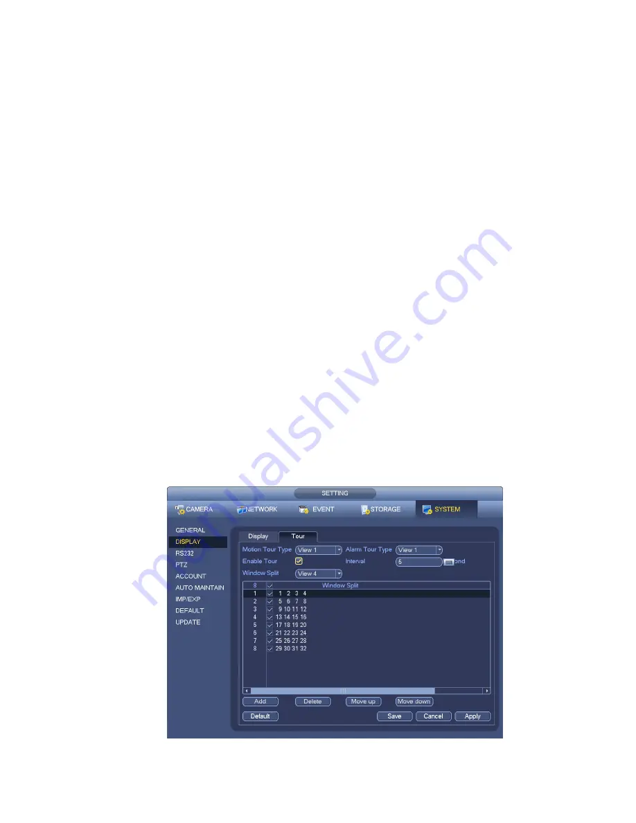
Figure 4-25
77
Channel name: Here is for you to modify channel name. System max support 25-digit (The value
may vary due to different series). Please note all your modification here only applies to NVR local
end. You need to open web or client end to refresh channel name.
Time display: You can select to display time or not when system is playback.
Channel display: You can select to channel name or not when system is playback.
Resolution: There are four options: 1
280×1024 (Default), 1280×720, 1920×1080, 1024×768. Please
note the system needs to reboot to activate current setup.
Image enhance: Check the box; you can optimize the margin of the preview video.
Click OK button to save current setup.
Note
The display parameter here has no effect on the record file and playback effect.
4.5.5
Preview Parameter
Set preview display mode, channel display sequence and tour setup.
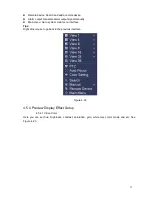
Set preview display mode: On the preview interface, right click mouse, you can view right-click menu.
Now you can select preview window amount and channel.
Set channel display mode: On the preview interface, if you want to change channel 1 and channel 16
position, please right click channel 1 video window and then drag to the channel 16 video window,
release button, you can change channel 1 and channel 16 position.
Tour setup: Here you can set preview window channel display mode and interval. Please follow the
steps listed below.
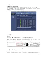
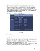
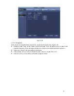
From Main menu->Setting->System->Display, you can see an interface shown as in Figure 4-25.
Here you can set tour parameter.
Enable tour: Check the box here to enable tour function.
Interval: Input proper interval value here. The value ranges from 1-120 seconds.
Monitor tour type: System support 1/8-window tour.
Alarm tour type: System support 1/8-window tour.
Summary of Contents for NVR-3202K
Page 1: ...i NVR 3202K User manual ...
Page 20: ...9 ...
Page 29: ...18 Figure 3 1 ...
Page 83: ...113 Figure 4 71 Figure 4 72 ...
Page 84: ...114 Figure 4 73 Figure 4 74 ...
Page 90: ...120 Figure 4 79 Figure 4 80 ...
Page 91: ...121 Figure 4 81 Figure 4 82 ...
Page 92: ...122 Figure 4 83 Figure 4 84 ...
Page 94: ...124 Figure 4 86 Figure 4 87 ...
Page 132: ...162 Figure 4 132 Figure 4 133 4 14 3 1 Add Modify Group ...
Page 172: ...202 The motion detect interface is shown as in Figure 5 52 Figure 5 52 Figure 5 53 ...
Page 173: ...203 Figure 5 54 Figure 5 55 Figure 5 56 ...
Page 177: ...207 Figure 5 60 Figure 5 61 ...


