Page 56
4 Series
Operator’s Manual
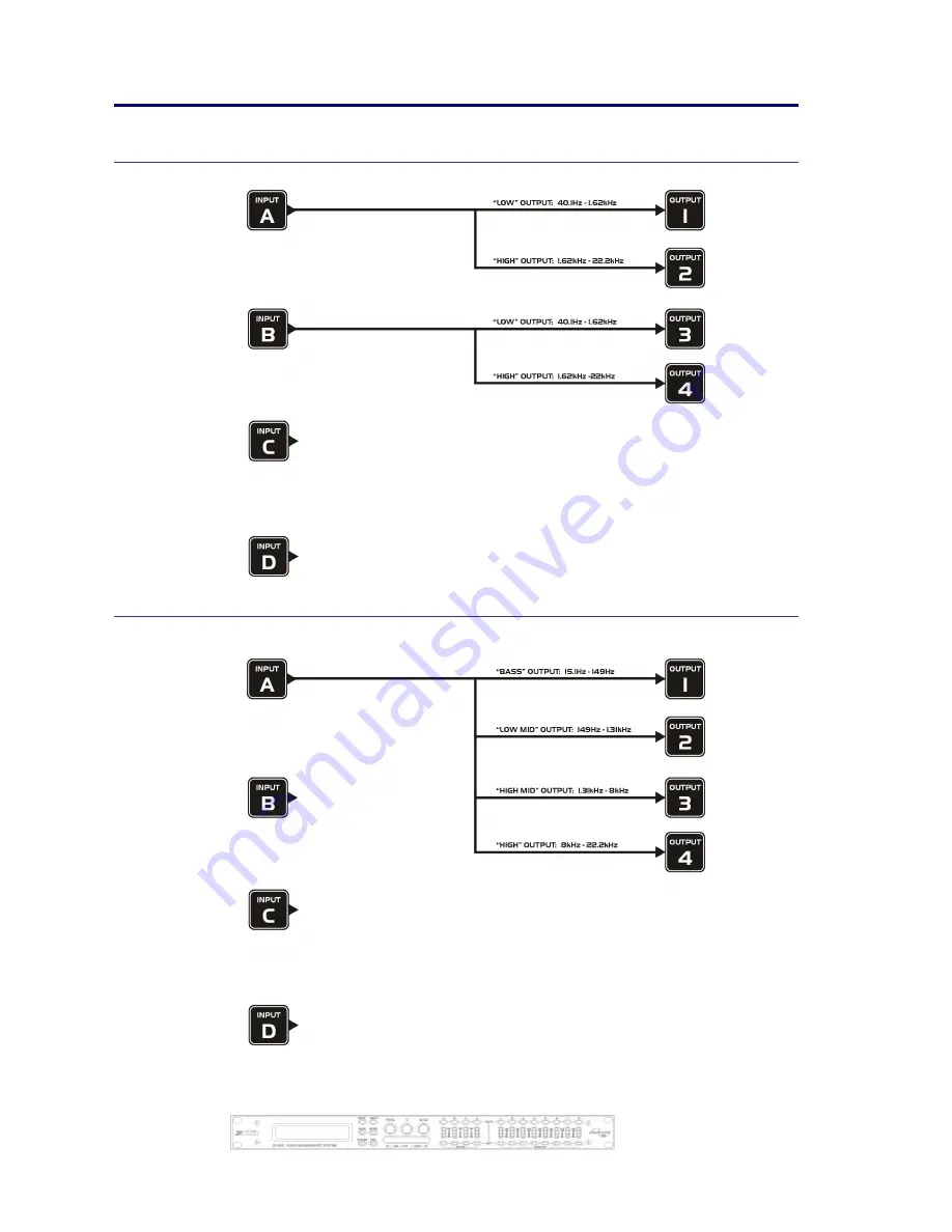
Appendix II – DP444 Default Crossover Configurations
2 x 2 Way
1 x 4 way
Page 1: ...1 10...
Page 2: ...Page 2 4 Series 4 Series 4 Series 4 Series Operator s Manual...
Page 3: ...SYSTEM SYSTEM Sub menu Used to view unit s status and select various global options such as PEQ Q or bandwidth units delay units and output metering point pre post mute SECURITY SECURITY SECURITY SECU...
Page 4: ...Assign Routing 15 Input Gain 16 Base Delay 16 Input Graphic EQ 16 Input Parametric EQ 16 Output Gain 17 Output Polarity 17 Output Delay 17 Output High Pass Filter 18 Output Low Pass Filter 18 Output...
Page 5: ...e GQ600 behaviour 37 The Special behaviour 38 Program Limiter and D Max Limiter 39 Program Limiter 39 D Max Clip Limiter 40 Setting Accurate Limiter Thresholds 42 Crossover Filter Slopes 43 Time Align...
Page 6: ...IQUE NE PAS ENLEVER NE PAS EXPOSER A LA PLUIE NI A L HUMITE Objects containing liquids such as vases must not be placed on this equipment It should not be necessary to remove any protective earth or s...
Page 7: ...tion about this or any other XTA product please contact us We look forward to hearing from you in the near future Unpacking the unit After unpacking the unit please check it carefully for any damage I...
Page 8: ...with AES EBU digital inputs and outputs and include a sample rate converter capable of accepting anything from 32kHz up tp 192kHz They may be controlled externally by XTA s proprietary WindowsTM softw...
Page 9: ...accept type I or type II PCMCIA SRAM cards and using an adapter Compact Flash cards This allows the unit to be cloned memory sets saved presets loaded and firmware updates installed Status LEDs The f...
Page 10: ...our Interface Guide available from the website Audio Outputs 3 pin XLR sockets are provided for each channel All are fully balanced pin 2 hot 3 cold 1 screen Note the legending on the panel to designa...
Page 11: ...T key to select Crossover Crossover Crossover Crossover sub sub sub sub menu menu menu menu and then press ENTER Use the BACK or NEXT key to select Design a crossover Design a crossover Design a cross...
Page 12: ...ompletely flexible channel routing Input Channel Makeup The diagram below shows the processing available on each of the four input channels before routing to the matrix Output Channel Makeup The diagr...
Page 13: ...numbers being the high part of the spectrum Default suggested crossover frequencies are shown by each output 2 x 3 way crossover Inputs A and B feed three outputs each with output 7 being fed from in...
Page 14: ...nputs A and B feed four outputs each with inputs C D being unused Default suggested crossover frequencies are shown by each output 1 x 8 way crossover Inputs A is fed to all eight outputs with initial...
Page 15: ...ever the current configuration is set to Press BACK until the display shows Design A Crossover Design A Crossover Design A Crossover Design A Crossover Routing Free Assign Routing Free Assign Routing...
Page 16: ...nd line of the screen denotes the Q behaviour of the graphic this setting behaves like a GQ600 with variable Q that is gentler at low cut boost values and sharpens at high cut boost values The alterna...
Page 17: ...put 1 Polar OP1 Output 1 Polar OP1 Output 1 Polar Polarity Polarity Polarity Polarity or Output Delay The maximum available delay between any input and output is 650 00mS For example if the input dela...
Page 18: ...Overlap High Low Freq Overlap High Low Freq Overlap High Low Freq Overlap will be displayed Note that to access the 48dB Octave filters parametric bands 8 9 need to be bypassed or set to 0dB If they a...
Page 19: ...tk 2 0mS Rel x16 22dB Atk 2 0mS Rel x16 22dB Atk 2 0mS Rel x16 22dB Atk 2 0mS Rel x16 22dB Attack Release Threshold Output D Max Clip Limiter The clip limiter on each output is designed to sit at a th...
Page 20: ...6 7 8 1 x 8 way Ganging 1 5 2 6 3 7 4 8 Ganging 1 5 2 6 3 7 4 8 Ganging 1 5 2 6 3 7 4 8 Ganging 1 5 2 6 3 7 4 8 4 x 2 way Ganging 1 3 5 7 2 4 6 8 Ganging 1 3 5 7 2 4 6 8 Ganging 1 3 5 7 2 4 6 8 Gangin...
Page 21: ...s System Status System Status Unit Locking Unit Locking Unit Locking Unit Locking Output Selection Output Selection Output Selection Output Selection Store a Memory Store a Memory Store a Memory Store...
Page 22: ...call Crossover Memory Recall Crossover Memory Recall Crossover Memory Recall Global Memory Recall Global Memory Recall Global Memory Recall Global Memory System Status System Status System Status Syst...
Page 23: ...wing angle of the screen LED Brightness LED Brightness LED Brightness LED Brightness Adjust the brightness of all the meters and button LEDs Temperature Alarm Temperature Alarm Temperature Alarm Tempe...
Page 24: ...EMORY MEMORY Sub Sub Sub Sub Menu Menu Menu Menu and its operation warrants a little more explanation Selecting to Store Store Store Store or Recall Recall Recall Recall using the Global Global Global...
Page 25: ...itionally include locations 1 and 6 in the list of memories available for recall as shown below In this way it is possible to recall part of a memory as long as it contains the memory type required No...
Page 26: ...25 feet between the PC and the unit If you experience problems with the connections consider selecting a slower baud rate selecting the Use Acknowledge Cmd option in AudioCore see the Remote Menu RS23...
Page 27: ...ise it and allow the update to be sent Download the latest version of the loader program and the unit software from www xta co uk and follow the instructions included with this zip file An RSS feed is...
Page 28: ...g from 1 again but designated shadow IDs with an s after the number 1s 1s 1s 1s Any ID can have multiple corresponding shadows RS485 Interface This interface is fitted as standard to all units and is...
Page 29: ...d to the serial port in use This configuration is shown below along with the required unit setup Both the converter and the required adapter cables are available from XTA The adapter is available in a...
Page 30: ...cables are available from XTA The adapter is available in a kit which includes a USB Serial converter the XLR to 9 pin adapter and the K2 ADE converter itself This complete kit is part number USB 485...
Page 31: ...ctly whilst the front panel one is via the processor allowing it to relay a little more information If it is flashing this means that AES inputs have been selected but have not locked Once a stable AE...
Page 32: ...ion and is of no importance to the user Pressing ENTER ENTER ENTER ENTER again will show AES Device Status AES Device Status AES Device Status AES Device Status V 96k0 V 96k0 V 96k0 V 96k0 V 96k0 V 96...
Page 33: ...e Xover Trim Mute As for Xover Trim but additionally output mutes are locked Input mutes remain active Changes Only Changes Only Changes Only Changes Only All parameters may be viewed but none may be...
Page 34: ...omentarily After a few seconds the unit will ask for a security code Use the EDIT EDIT EDIT EDIT keys in the same manner as for entering lock codes see page 33 for details and enter 2121 The display w...
Page 35: ...s possible It s good practice to note on the card the date of the battery replacement Most cards only allow for ten minutes or so of unassisted backup so be sure to have the new battery to hand when r...
Page 36: ...to copy the software and the presets Be sure to set the Write Protect switch on the card ON before removal as data corruption can occur as the card is pulled out of the slot Loading Data into Destina...
Page 37: ...o offer the best of both worlds in terms of corrective control and creative control This is achieved by manipulation of the bandwidth of the filters depending on the amount of cut or boost being appli...
Page 38: ...lues of cut boost but is also less peaky when high levels of boost are applied ensuring the flattest response when adjacent faders are adjusted Consider the group of faders gently boosted as shown bel...
Page 39: ...th all limiters using too fast an attack or release time will result in excessive low frequency distortion In the Design a Crossover Design a Crossover Design a Crossover Design a Crossover sub menu t...
Page 40: ...fed through the monitor desk and the gain controlled by adjusting the fader The sidechain is formed by the feedback path between the engineer s ears checking the level and his brain instructing his h...
Page 41: ...just following the traditional limiter has only two parameters to adjust OP1 Output 1 ClipLim OP1 Output 1 ClipLim OP1 Output 1 ClipLim OP1 Output 1 ClipLim Rel Medium 10dB Above Rel Medium 10dB Above...
Page 42: ...iters are capable of performing all these tasks The only parameter that the user must set manually is the threshold and it is crucial that this is done correctly Consider the table below dB Ratio Vrms...
Page 43: ...with absolute accuracy since component tolerance problems do not occur Please see page 18 for details of how to adjust the high and low pass crossover filter settings Time Alignment A further advanta...
Page 44: ...automatically set the gain back to 0dB Each filter type will be explained in turn in the following section Standard Parametric EQ InA Input A PEQ 1 InA Input A PEQ 1 InA Input A PEQ 1 InA Input A PEQ...
Page 45: ...gain boosts only are show below Remember that Q is 1 Bandwidth so the higher the Q the lower the Bandwidth and the smaller the range of frequencies affected Note that Q settings above 0 75 will resul...
Page 46: ...ncies affected Note that the response is fundamentally NOT a flat topped response so it is not constructed from a high pass and low pass See previous page for details of how to construct a flat topped...
Page 47: ...gher the Q the faster the transition Phase Filter InA Input A PHS 1 InA Input A PHS 1 InA Input A PHS 1 InA Input A PHS 10 0 0 0 1k00Hz 150 1k00Hz 150 1k00Hz 150 1k00Hz 150 Phase Phase Phase Phase Rem...
Page 48: ...he filter type The low and high pass variable Q filters have adjustable frequency and Q or Bandwidth controls The Q control adjust the damping of the filter so that low Q settings show less overshoot...
Page 49: ...ignificantly steeper in roll off than number 1 as would be expected However number 3 is a 12dB Octave Butterworth filter with an Elliptical Low Pass filter following it This produces a combined roll o...
Page 50: ...Filters Filters 1 of each per output Freq Range HPF 10Hz 16kHz 1 36 octave steps Freq Range LPF 35Hz 22kHz 1 36 octave steps Responses 1st Order 6dB Oct Bessel Butterworth Linkwitz Riley 12 24 48dB Oc...
Page 51: ...not covered by this warranty This warranty is exclusive and no other warranty is expressed or implied XTA is not liable for consequential damages Options and Accessories Part Number Part Description I...
Page 52: ...Output Gain 17 Parametric EQ 16 18 Polarity 17 Elliptical Filter 49 F Features 8 Flat Topped EQ 45 Free Assign 15 Front Panel 9 G Ganging Inputs 20 Ganging Outputs 20 Global Memory Menu 23 GQ600 37 Gr...
Page 53: ...10 Release Times 39 Resonant Filter 48 Routing 15 Basic 12 Free Assign 15 Presets 12 RS232 Interface 26 RS485 Interface 29 S Security 33 Security Menu 23 Shadow IDs 28 Shelving EQ 45 Shipping 7 Sidec...
Page 54: ...Page 54 4 Series 4 Series 4 Series 4 Series Operator s Manual Appendix I DP446 Default Crossover Configurations 2 x 3 Way 3 x 2 way...
Page 55: ...Operators Manual Page 55 2 x 2 Way 2 Aux 1 x 6 way...
Page 56: ...Page 56 4 Series 4 Series 4 Series 4 Series Operator s Manual Appendix II DP444 Default Crossover Configurations 2 x 2 Way 1 x 4 way...
Page 57: ...Operators Manual Page 57 4 x 1 way...
Page 58: ...Page 58 4 Series 4 Series 4 Series 4 Series Operator s Manual Appendix III DP424 Default Crossover Configurations 2 x 2 Way 1 x 4 way...