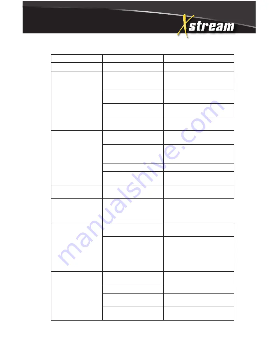
Xstream HW152EMD Operation Manual Download Page 31

31

troubleshooting

SYMPTOM

PROBABLE CAUSE

REMEDY

Oil leaking from unit.

Worn seals or o-rings.

Contact Customer Service.

Detergent will not 

siphon .

Detergent strainer is not 

completely submerged in 

detergent solution.

Check, submerge if necessary.

Detergent strainer 

obstructed.

Inspect, clean or replace.

Detergent hose cut, 

obstructed or kinked.

Inspect, clean or replace.

Detergent adjusting knob 

turned to closed position.

Open adjusting knob. Refer to 

“Cleaning with Detergents”.

Detergent will not 

siphon into the Low 

Pressure Mode

Adjustable grip on lance is 

not in low pressure mode.

Turn grip clockwise to move to 

low pressure

Too many high pressure 

hose extensions attached to 

the water outlet.

Use one extension maximum.

Nozzle assembly is plugged. Clean or replace.

Ball & Spring in Venturi 

stuck.

Remove, clean or replace.

Water flows back into 

detergent container.

Check valve missing or 

corroded.

Remove, clean or replace.

Water flows from the 

nozzle when the trigger 

gun is locked in the 

“OFF” position

Trigger gun is 

malfunctioning.

Repair or replace.

Water is leaking under 

heat exchanger coil.

Coil drain plug is not 

installed.

Install.

Safety Relief device is 

relieving caused by an 

unloader or pressure switch 

malfunction.

1.Detect and correct unloader or 

pressure switch problem.

2. Replace safety relief device. 

NEVER run unit without safety 

relief device. Doing so can cause 

an explosion!

Burner will not ignite

Switch is not in “Burner” 

position.

Check switch position.

No voltage.

Contact Customer Service.

Out of fuel.

Refuel. (Reset burner primary 

control on cad cell options.)

Fuel pickup screen 

obstructed.

Consult Service.

Summary of Contents for HW152EMD

Page 1: ...operation manual HW152EMD HW204EMD ELECTRIC HOT WATER PRESSURE WASHER...

Page 2: ...le Review 18 Nozzle Connection 19 Water Supply 20 Unloader 20 Thermal Relief Valve 20 Pre Start Inspection Procedures Operation 21 Flushing the System 21 Start Up Cold Water Operation 23 Hot Water Ope...

Page 3: ...8 49 Heat Exchanger Blower Motor 51 Boiler Assembly 53 Gun Wand Hose Assembly 54 Fuel Tank 55 Fuel Pump 55 Fuel Solenoid 56 Electric Box Assembly for HW1115EMD and HW152EMD 58 Electric Box Assembly fo...

Page 4: ...owner s manual thoroughly will help avoid any personal injury or damage to your pump By knowing how best to operate this machine you will be better positioned to show others who may also operate the u...

Page 5: ...ce line 1 866 770 1711 for information on servicing always provide the product model and identification numbers You will need to locate the model and serial number for the pump and record the informat...

Page 6: ...azard which if not avoided might result in minor or moderate injury NOTICE indicates a situation that could result in equipment damage Follow safety messages to avoid or reduce the risk of injury or d...

Page 7: ...e certain the unit is receiving proper voltage Before plugging the unit into a compatible power source be certain the switch is in the OFF position Disconnect when not in use Do not modify plug provid...

Page 8: ...uel indoors or in a poorly ventilated area Burner Fuel Tank Use No 1 or No 2 fuel oil diesel or kerosene Do not use gasoline crankcase drainings or oil containing gasoline or solvents Do not operate t...

Page 9: ...t persons or self This product is to be used only by trained operators Always keep operating area clear of all persons Close supervision is necessary when used near children DO NOT allow children to o...

Page 10: ...he unit must always be warm enough to ensure there is no ice formation in the pump Do not start the pressure washer if it has been transported in an open or under heated vehicle without first allowing...

Page 11: ...sing cleaning detergents Keep all detergents out of the reach of children ALWAYS wear protective goggles when operating the unit to shield the eyes from flying debris and detergents DO NOT direct spra...

Page 12: ...see any fuel oil or water leaks from the machine DO NOT resume operation until the unit has been in spected and repaired by a qualified service person Place unit in a clean dry flat area for servicin...

Page 13: ...ank 4 High Pressure Pump w Unloader 5 Flat Free Wheels 6 Switch On Off Burner 7 Burner Air Regulation 8 Brake 9 High Pressure Hose 10 Trigger Safety Lock 11 Trigger Gun 12 Insulated Lance 13 Lance 14...

Page 14: ...be exposed to rain snow or freezing temperatures If any part of the unit becomes frozen excessive pressure may build up in the unit which could cause it to burst resulting in possible serious injury...

Page 15: ...outlet have a proper outlet installed by a qualified electrician Do not use any type of adaptor with this product 5 GROUND FAULT CIRCUIT INTERRUPTER PROTECTION a SINGLE PHASE If this pressure washer...

Page 16: ...plugs and 4 pole cord connectors that accept the plug from the product Use only extension cords that are intended for outdoor use These extension cords are identified by a marking Acceptable for use...

Page 17: ...ous damage To determine spray fan refer to the actual num ber stamped on the nozzle The first two digits indicate the spray fan in degrees i e 00 0 15 15 40 40 1 The 0 nozzle RED This is a blasting no...

Page 18: ...irst two digits indicate the spray 1 The0 nozzle RED Thisisa stream of water Be cautious not recommended for use on with adhesive backings Us stubborn stains from concret from equipment and cleanin 2...

Page 19: ...ated on the pressure washer nameplate You can check GPM by timing how long it takes to fill a 5 gallon container c Incoming water temperature must not exceed 125 F Excessive pump damage may result if...

Page 20: ...Customer Service installation preparation 13 al 13 INSTALLATION PREPARATION coming water requirements listed below essure must be a minimum of 20 pounds per square inch PSI aximum of 125 PSI A typical...

Page 21: ...hed turn off the water supply and connect the high pressure hose to the water outlet of the unit 4 Connect the trigger gun and lance assembly to the high pressure hose 5 Turn on the water supply CAUTI...

Page 22: ...LY Replace hose before starting the unit See Risk of In jection or Severe Cutting Injury pg 9 Be sure that all damaged parts are replaced and that the mechanical problems are corrected prior to operat...

Page 23: ...sibility of burns NOTICE While spraying it is normal for the burner to fire intermittently The high limit switch will cause combustion to cease when the temperature of the discharged water exceeds the...

Page 24: ...rinse a small section at a time 6 To rinse lock the trigger gun in the OFF position securely quick connect the desired high pressure nozzle into the end of the wand Unlock the trigger gun and spray It...

Page 25: ...eriod of three minutes to cool the heat exchanger and high pressure hose Insufficient cool down period of the high pressure hose will cause excessive wear and eventual rupturing of the hose 3 Move the...

Page 26: ...air temperatures To assure maximum combustion efficiency at colder temperatures and higher altitudes it will be necessary to adjust the air supply to the combustion chamber A smoke spot test is recom...

Page 27: ...ers b One gallon of antifreeze Use an environmentally safe antifreeze c Water supply d Three foot hose 1 2 3 4 I D with a 3 4 inch male garden hose fit ting 2 Procedure a To start winterizing unit mus...

Page 28: ...PROCEDURE a Shut the unit and water supply off b Relieve system pressure by pointing the trigger gun in a safe direction and squeezing the trigger until water flow ceases to exit the nozzle c Disconne...

Page 29: ...ter water separator X Inspect fuel pump filter X Replace fuel nozzle X Check burner air adjust ment X X X X Check burner electrodes X Test water pressure X X X X Test fuel pressure X X X X Test water...

Page 30: ...ve screen clean or replace Pump sucking air Prime eliminated Tighten all water intake connections Eliminate leaks in intake line Adjustable Grip on Lance is not in high pressure mode Turn grip counter...

Page 31: ...sion maximum Nozzle assembly is plugged Clean or replace Ball Spring in Venturi stuck Remove clean or replace Water flows back into detergent container Check valve missing or corroded Remove clean or...

Page 32: ...burner air adjustment Adjust as explained on page 26 Ignition transformer failure Replace Ignition electrodes damaged or worn With unit running and trigger gun closed look through burner sight glass...

Page 33: ...Dirty fuel nozzle Replace Fuel pickup screen obstructed Consult Customer Service Improper air adjustment setting Adjust as explained on page 26 Scale build up in heat exchanger coil Consult your Cust...

Page 34: ...ic Manifold Forged Brass Valves Stainless Steel Unloader Preset Heat Dump Valve Relieves heated water during unloader bypass stage Detergent Injector Adjustable High Pressure Burner Fuel System Fuel T...

Page 35: ...ch Shuts off burner fuel supply when outlet water temp exceeds 210 F 99 C Fuel Solenoid 120 Volt 240 Volt Safety Relief Relieves excess system pressure Unit Net Weight Lbs Kg 299 136 316 143 Unit Ship...

Page 36: ...36 flow chart 57 6 013 FLOW CHART parts list...

Page 37: ...protects the op erator from danger The safety system contains a HIGH TEMPERATURE LIMIT SWITCH 16 which senses the water temperature and shuts off the fuel supply to the burner if it gets too hot If th...

Page 38: ...38 frame assembly 59 10 Copyright 2013 FRAME ASSEMBLY parts list...

Page 39: ...mbly N A 1 9 Bolt 27 0066 8 10 Bolt 27 9550 1 11 Bolt 27 0015 4 12 Push Pull Toggle Clamp 33 0400 1 13 Brake Bracket 20 1314A02 1 14 Lockwasher 29 0007 4 15 Grommet 33 0001 5 16 Nozzle Holder 20 1276A...

Page 40: ...40 motor pump assembly 61 12 Copyright 2013 MOTOR PUMP ASSEMBLY parts list...

Page 41: ...2 0438 1 8 Capaciter Run 2000 32 0450 1 Capaciter Run 1000 1500 32 0413 1 9 Capaciter Start 2000 32 0449 1 Capaciter Start 1500 32 0412 1 Capaciter Start 1000 32 0411 1 10 Strap 52 0042 11 O Ring 25 0...

Page 42: ...42 PUMP aSSEMBLY 63 14 Copyright 2013 PUMP ASSEMBLY 3 0383 3 0384 TORQUE SPECS Position FT LBS 2 11 3 37 22 18 31 7 4 parts list...

Page 43: ...Compaction Ring 46 1311 3 11 Low Pressure Seal see 70 0501 SEE KIT 3 12 O Ring see 70 0501 SEE KIT 3 13 Retainer Ring 46 1312 3 14 O Ring 25 0663 3 15 Oil Seal 46 1313 3 16 Crankcase N A 1 17 Needle...

Page 44: ...w 27 8886 1 33 Crankshaft N A 1 34 Ball Bearing 48 0063 1 35 Snap Ring 46 1506 1 36 O Ring 25 0603 1 37 Crankshaft Cover 46 1507 1 REPLACEMENT KITS DESCRIPTION ITEMS OF ASSEMBLIES OF CYLINDERS 70 0501...

Page 45: ...UNLOADER 8 0628 ITEM DESCRIPTION PART QTY 1 Screw N A 1 2 Plastic Knob N A 1 3 Knob N A 1 4 Spring N A 1 5 Spring Seat N A 1 6 Valve Rod N A 1 7 Support Ring N A 1 8 O Ring 25 0651 1 9 Set Screw 8 047...

Page 46: ...et Connector N A 1 25 Inlet Banjo Bolt 8 0595 1 26 O Ring 25 0602 1 27 Inlet Connector SEE KIT 1 28 Swivel Nut SEE KIT 1 29 Filter 19 0001 1 30 O Ring 25 0654 1 31 By Pass Housing N A 1 32 O Ring N A...

Page 47: ...06 18 Copyright 2013 PRESSURE SWITCH 22 0171 PRESSURE SWITCH 22 0171 REF DESCRIPTION PART QTY 1 Pressure Switch 22 0171 1 2 Screw N A 4 3 Cover N A 1 4 O ring See 70 0306 N A Sep 1 5 Micro Switch N A...

Page 48: ...6 Ba 7 O r COIL DRAIN PLUG 850 0218 COIL DRAIN PLUG 850 0218 REF DESCRIPTION PART 1 Bolt 27 9526 2 Retaining Cable 33 0260 3 Snap Ring 33 0261 4 Hand Wheel 16 0239 5 Plug 24 0147 6 Back up Ring 25 04...

Page 49: ...49 69 20 Copyright 2013 HEAT EXCHANGER BLOWER MOTOR heat exchanger blower motor parts list...

Page 50: ...Tee 23 0058 1 10 High Pressure Hose 15 0090 1 11 Nut 30 3022 2 12 Elbow 23 0237 2 13 Fuel Hose 15 0147 2 14 Elbow 27 8898 2 15 Fuel Hose 15 0333 1 16 Elbow 23 0287 2 17 Fuel Pump 3 0020 1 18 Coupler...

Page 51: ...51 boiler assembly 71 22 pyright 2013 BOILER ASSEMBLY parts list...

Page 52: ...2 Exhaust Chimney 20 1264 1 13 Electrode Assembly inc 5 14 21 850 0415 1 14 Cone 20 0373 1 15 Bolt 27 8878 8 16 Electrode Plate 38 0065 1 17 Sight Glass 33 0252 1 18 Snap Ring 33 0254 1 19 Washer 28 0...

Page 53: ...et 17 0004 1 4 Hose 15 0145 1 5 Quick Connect 17 0006 1 6 Lance Assembly 16 0366 1 7 Nozzle 00040 1000 18 0397 1 Nozzle 15040 1000 18 0399 1 Nozzle 40040 1000 18 0401 1 Nozzle 00030 1500 18 0387 1 Noz...

Page 54: ...K UP 6 NIPPLE 7 DECAL CAUTION RISK OF FIRE SEE 71 0058 8 FUEL TANK 9 DRAIN PLUG 26 Copyright 2013 FUEL TANK HSE_HSP SMALL FUEL TANK ASSY 110512 C FUEL TANK ASSEMBLY ITEM DESCRIPTION Mi T M QTY 1 FUEL...

Page 55: ...5 4 Strainer 19 0034 5 Cover Gasket 26 0109 6 Plug 24 0044 7 Body N A 8 Plug 24 0082 0MHSP013 44 0101 12 FUEL SOLENOID 44 0101 REF DESCRIPTION PART 1 Solenoid Complete 120V 44 0101 2 Solenoid Body 46...

Page 56: ...56 electric box assembly for hw1115emd and hw152emd 77 28 Copyright 2013 ELECTRIC BOX ASSEMBLY FOR C11EAHW AND C152EGHW HW1115EMD AND HW152EMD parts list...

Page 57: ...ectrical Locknut 32 0292 1 9 Cam Switch 1500 32 0679 1 Cam Switch 1000 32 0434 1 10 Bolt 27 9526 14 11 Electrical Box Cover 20 1309A01 1 12 Terminal Strip 32 0436 1 13 Screw 27 8835 4 14 Nut 30 6001 3...

Page 58: ...58 electric box assembly for hw204emd 79 30 Copyright 2013 ELECTRIC BOX ASSEMBLY FOR C204EMHW HW204EMD parts list...

Page 59: ...32 0437 4 8 Cord Relief 9 0046 1 9 Bolt 27 8807 1 10 Electrical Locknut 32 0292 1 11 Cam Switch 32 0435 1 12 Bolt 27 9526 10 13 Electric Box Cover 20 1309A01 1 14 Nut 30 6001 3 15 Star Washer 28 1009...

Page 60: ...60 wire schematic for hw1115emd and hw152emd 81 32 pyright 2013 WIRE SCHEMATIC FOR C11EAHW AND C152EGHW HW1115EMD AND HW152EMD parts list...

Page 61: ...61 wire diagram for hw1115emd and hw152emd 82 33 Copyright 2013 WIRE DIAGRAM FOR C11EAHW AND C152EGHW HW1115EMD AND HW152EMD parts list...

Page 62: ...62 wire schematic for hw204emd 83 34 ht 2013 WIRE SCHEMATIC FOR C204EMHW HW204EMD parts list...

Page 63: ...63 wire diagram for hw204emd 84 35 Copyright 2013 WIRE DIAGRAM FOR C204EMHW HW204EMD parts list...

Page 64: ...or Shields Pulleys For One 1 Year from the date of original purchase Adjustable Thermostat GFCI Cord Selector switch Starter Contactor Overload For Six 6 months from the date of original purchase Igni...

Page 65: ...asive or corrosive environments or under conditions causing pump cavitation are not warranted Failure to follow recommended operating and maintenance procedures also voids warranty 4 The use of other...

Page 66: ...66 If you need assistance with the assembly or operation of this Pressure Washer please call 1 866 770 1711...

Reviews: