background image

ForeSite SS Hardware

18

Set-Up Instructions

1. 

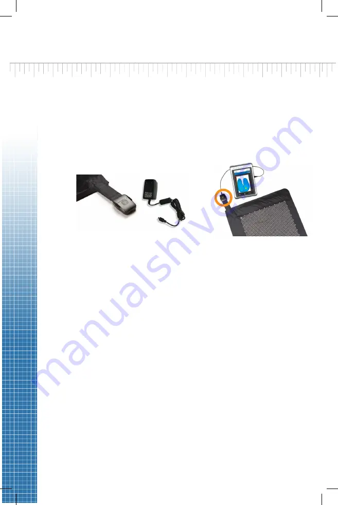
Begin by ensuring both the ForeSite SS tablet and the X4 are fully 
charged.  Recommended charge time to ensure a full charge is 2-3 
hours for both devices. For the X4, connect the micro-USB on the X4 
power supply to the micro-USB input on the X4, as shown in Figure 
1. For the ForeSite SS tablet, connect the tablet power supply and 
cord to the tablet as shown in Figure 2.

Warning:  Use only XSENSOR approved power supplies with ForeSite SS. 
Do not connect any other USB device or cable to the X4.

2. 

Inspect the sensor pad covering material and cable for signs of 
damage. These include, but are not limited to, tears, punctures, 
cracked enclosures, and/or exposed wiring. If damage is identified or 
suspected, contact XSENSOR for repair (see Appendix #4)

Warning:  Do not attempt live pressure imaging if the sensor pad is 
damaged or soiled. Refer to the Maintenance section of this user guide 
for more information on cleaning. 

3. 

Connect the X4 to the sensor pad for Wired Set-up, plug the micro 
USB into the X4 enclosure and the other end into the tablet. 

4. 

For wireless setup, connect the X4 to the sensor pad via bluetooth 
settings. On the tablet, go to Bluetooth devices and ensure 
Bluetooth is on. Your tablet will search for discoverable Bluetooth 
devices. Pair it with the sensor (device will start with WSPK).

Figure 1

Figure 2

Summary of Contents for ForeSite SS

Page 1: ...User Guide...

Page 2: ...Corporation All rights reserved The XSENSOR Pressure Imaging System is protected by copyright law Unauthorized reproduction or redistribution of XSENSOR software is prohibited No part of this documen...

Page 3: ...oreSite SS Tablet System 21 Display Tablet Specifications 27 Maintenance 30 Storage Transport 30 Cleaning 32 Cleanable Sensor Instructions 33 FORESITE SS SOFTWARE 37 Introduction 39 Quick Start 39 Use...

Page 4: ......

Page 5: ...Introduction The ForeSite SS System 3 Overview 3 Intended Use 3 Product Compliance 4 Safety Standards 4 Emission Immunity Standards 5 Warnings Cautions 11...

Page 6: ......

Page 7: ...ing pressure ulcers which can form when muscles and soft tissue press against surfaces such as a chair or a bed As such preventative measures must be taken in order to reduce these risks ForeSite SS p...

Page 8: ...ForeSite SS is intended for use by healthcare professionals only ForeSite SS must be installed and used as described in this user manual This system is designed in compliance with medical safety stan...

Page 9: ...ncreased emissions or decreased immunity ForeSite SS complies with Part 15 of the FCC Rules Operation is subject to the following conditions 1 This device may not cause harmful interference and 2 This...

Page 10: ...roup 1 The ForeSite SS system uses RF energy only for its internal function Therefore its RF emissions are very low and are not likely to cause any interference in the nearby electronic equipment RF e...

Page 11: ...help prevent electromagnetic interference by maintaining a minimum distance between portable and mobile RF communications equipment transmitters and the ForeSite SS as recommended below according to...

Page 12: ...than the compliance level in each frequency rangeb Interference may occur in the vicinity of known RF transmitting devices and equipment marked with the following symbol NOTE 1 At 80 MHz and 800 MHz t...

Page 13: ...r Floors should be wood concrete or ceramic tile If floors are covered with synthetic material the relative humidity should be at least 30 Electrical fast transient burst IEC 61000 4 4 2 kV for power...

Page 14: ...dip in UT for 25 cycles 5 UT 95 dip in UT for 5 sec Mains power quality should be that of a typical commercial or hospital environment If the user of the equipment requires continued operation during...

Page 15: ...e for information on cleaning 4 Warning The ForeSite SS System is not intended for long term use 5 Warning The ForeSite SS System is intended for use by health care professionals only 6 Warning To red...

Page 16: ...e client from a seated position 13 Warning ForeSite SS Tablet may become hot with extended use in a hot environment Handle with care and avoid contact with hot surfaces Do not place tablet on any body...

Page 17: ...24 Caution For information regarding the safe disposal of the ForeSite SS Display Tablet or Sensor at the end of product life contact a local XSENSOR representative or XSENSOR directly see Appendix 4...

Page 18: ...No on De ple...

Page 19: ...play Tablet Specifications 27 Power Supply Specifications 29 X4 Lithium Ion Battery 29 Specifications Maintenance 30 Storage Transport 30 Cleaning 32 Cleanable Sensor Instructions 33 ForeSite SS Label...

Page 20: ...ForeSite SS Hardware 16...

Page 21: ...umentation USB Flash Drive ForeSite SS Desktop Software ForeSite SS User Guide G ForeSite SS Quick Start Guide not shown H ForeSite SS Carry Case not shown See Appendix 2 for the ForeSite SS Desktop S...

Page 22: ...al and cable for signs of damage These include but are not limited to tears punctures cracked enclosures and or exposed wiring If damage is identified or suspected contact XSENSOR for repair see Appen...

Page 23: ...rotrusions that may puncture tear the sensor pad covering material If the sensor has one of the following markings it is cleanable as per the Cleanable Sensor Instructions section of this User Guide F...

Page 24: ...arging connecting and powering ON your second X4 North American Danish Australian Indian British Israeli Continental European Italian Japanese Swiss NOTE Ensure that the power adaptor corresponds to t...

Page 25: ...umentation USB Flash Drive ForeSite SS Desktop Software ForeSite SS User Guide F ForeSite SS Quick Start Guide not shown G ForeSite SS Carry Case not shown See Appendix 2 for information on ForeSite S...

Page 26: ...nance section of this user guide for more information on cleaning 3 Connect the SPK to the sensor pad cable connection point aka CONN as shown in Figure 2 The SPK and CONN are connected correctly when...

Page 27: ...the sensor protective sleeve Figure 2 6 Power ON the tablet by pressing the ON OFF button for at least 3 seconds Figure 3 The power LED indicator on the display panel will turn blue Once the tablet i...

Page 28: ...ection of two USB SPKs to the tablet Dual Sensor Pad Systems Dual sensor pad systems include all the same components as listed above for the single pad systems with the exception of 1 additional Press...

Page 29: ...latform The high resolution sensor pad system is connected as shown in Figure 5 Turn on the X3 Pro Platform by pressing the power button until the LED turns on The LED on the sensor pack should also t...

Page 30: ...ded in your country see chart XSENSOR is not responsible for damages that may sustain if an incorrect power source is used If a different power adaptor is required for your country please contact XSEN...

Page 31: ...1280 x 800 pixels Mechanical and Environment Weight 1 2 kg Shock Rugged mobile shock Vibration Rugged mobile vibration Drop 1 2m 4 Certifications CE FCC EN 60601 1 Power Management Power Input 12 VDC...

Page 32: ...ors COMPONENTS FUNCTION 1 Docking Connector Not applicable for ForeSite SS 2 USB For connectivity and or USB storage devices 3 LAN HDMI LAN HDMI Out combo connector 4 Mic in Line Out Not applicable fo...

Page 33: ...DC Nominal Capacity 2400 mAh Caution Risk of fire explosion or burns Do not short circuit crush heat above 100C incinerate or disassemble the battery Caution Charge only using the XSENSOR X4 and Globt...

Page 34: ...rs may ONLY be performed by the manufacturer or the manufacturer s authorized representative The device may still be used successfully if it is not calibrated the frequency of calibration is at the di...

Page 35: ...system storage and transportation Ambient Temperature 4 to 140 F 20 to 60 C Relative Humidity 10 to 90 non condensing Atmospheric Pressure 0 50 to 1 06 bar Do not place heavy objects on top of a fold...

Page 36: ...applies to the connector ends of USB cords and any other electrical connector A clean dry cloth may be used to clean these portions of the cords only but ONLY while they are unplugged The non connecto...

Page 37: ...e carefully with a damp cloth and isopropyl alcohol if absolutely necessary NEVER use a steam cleaner on the sensor After cleaning the sensor allow to air dry COMPLETELY before returning to use Cautio...

Page 38: ...e with the brush 5 Wet a soft cloth with tap water 6 Wipe off residual cleaning solution with the wet cloth 7 Allow surface to dry 8 Wet a soft cloth with 1 10 cleaning solution 9 Wipe the sensor with...

Page 39: ...with hot surfaces Do not place tablet on any body surface Place on a hard surface and do not impede airflow Approved for sale in the European Economic Area RCM Regulatory Compliance Mark approved for...

Page 40: ......

Page 41: ...ForeSite SS Software Introduction 39 Quick Start 39 User Roles Security 41 Administrative Settings 41 Standard Settings 45 Sensors 47 Client Management 48 Pressure Imaging 49 Gallery Management 51...

Page 42: ......

Page 43: ...are has been properly setup as per the instructions in the Hardware section of the guide you are ready to get started with your ForeSite SS software 1 Ensure your ForeSite SS tablet is fully charged 2...

Page 44: ...t the Sensors tab to ensure your sensor is connected and active If your hardware was properly configured your sensor will appear in the list and a pressure image will be live as shown in the image to...

Page 45: ...he software As such all ForeSite SS users regardless of their role must provide a username and password in order to access the system New users can only be created by the Administrator user role This...

Page 46: ...Language dropdown To Delete Users 1 Select the user to open the user profile 2 Select the Delete User button at the bottom of the screen All client files associated with a user account must be transfe...

Page 47: ...he ForeSite SS database you would like to import into the tablets USB port 3 Select Restore 4 Select the database file from which you would like to restore your database 5 Select Open Activity Log To...

Page 48: ...ss to use as the sender for file sharing 4 Enter the password for the above email address NETWORK CONFIGURATIONS To Disable Enable Bluetooth Connectivity This feature allows seamless connectivity to w...

Page 49: ...MAGE LEGEND AND SCALE To Change the Pressure Unit of Measurement 1 Select the preferred unit of measurement from the Pressure Units dropdown menu To Set the Upper and Lower Pressure Limits The thresho...

Page 50: ...preferred unit of measurement from the Contact Area dropdown menu PRESSURE VIDEO RECORDING To Set the Maximum Recording Time 1 Enter the desired lower upper recording time in minutes next to Maximum...

Page 51: ...this user guide 2 Select Refresh to scan for a sensor connection 3 If ForeSite finds your sensor it will appear in the list and display a live thumbnail of the pressure image Select the checkbox of t...

Page 52: ...file is the first step in beginning pressure imaging The Live Image tab will be inactive until a client file is created and opened Begin by selecting the main Clients tab To Create a New Client File 1...

Page 53: ...r your snapshot 3 Select to capture notes for your snapshot Snapshots are automatically saved to Gallery as soon as they are taken To Take a Pressure Image Recording 1 Toggle the camera recorder icon...

Page 54: ...ce it 3 Select the desired type from the list Note Select the text area below the Note selection to enter text Coccyx LIT left ischial tuberosity RIT right ischial tuberosity RGT right greater trochan...

Page 55: ...ure image data you would like to share export 5 Select the envelop icon to email or disc icon to save to an external drive The email option will only be displayed if this administrative setting is tur...

Page 56: ...t an item from the Gallery tab to view it on the main Review tab To View Notes Captured on a Gallery Item where notes have been previously captured 1 Select the note icon on the pressure image to expa...

Page 57: ...with the same red arrows icon that appears on the capture icon To View Compared Pressure Images as a Quadrant or in Columns 1 Once the Compare feature has been initiated from the Gallery described abo...

Page 58: ......

Page 59: ...Appendixes Appendix 1 Troubleshooting 56 Appendix 2 The Desktop System 58 Appendix 3 Contact Information 64...

Page 60: ...ing with the sensor Once a connection is established the sensor icon in the software will turn green 5 If the software still does not communicate with the sensor pad check to see if the sensor pad has...

Page 61: ...the sensors Navigate to the Sensors tab in Settings to re establish the sensor s connection The video capture session was interrupted at due to a sensor communication error Navigate to the Sensors tab...

Page 62: ...g Sensor Pad B Wireless Sensor Pack X4 C X4 Power Supply for recharging D Documentation USB Flash Drive ForeSite SS Desktop Software ForeSite SS User Guide E ForeSite SS Quick Start Guide not shown F...

Page 63: ...pre loaded files on USB If not automatically prompted navigate to USB drive on PC Open folder called ForeSite SS Desktop Software and run installation file called InstallForeSiteSSDesktop Follow the...

Page 64: ...ore the subject makes contact with the sensor ensure that they do not have any sharp objects or protrusions that may puncture tear the sensor pad covering material Warning Neither sensor pads nor prot...

Page 65: ...SENSOR PAD SYSTEMS A Pressure Imaging Sensor Pad B Sensor Pack SPK C Power Supply and Power Cord D Documentation USB Flash Drive ForeSite SS Desktop Software ForeSite SS User Guide E ForeSite SS Quic...

Page 66: ...live pressure imaging if the sensor pad is damaged or soiled Refer to the Maintenance section of this user guide for more information on cleaning 3 Connect the SPK to the sensor pad cable connection...

Page 67: ...sure distribution while standing Accuracy is 10 full scale For use with ForeSite SS Sensor Pad Sensing Area Resolution Pressure Range Cleanable PX100 48 144 02 24 x72 0 5 5 50 10 200 mmHg No PX100 64...

Page 68: ...Use misuse of the ForeSite SS System Replacement of damanged lost system components Replacement power cords designed for different countries Software troubleshooting General concerns questions or com...

Page 69: ......

Page 70: ...xsensor com Innovators in Pressure Imaging ASY 05 00005 02 ASY 05 00005 02...

Reviews: