© XPAND, All Rights Reserved.
www.xpandvision.com
System Overview
The XPAND Passive 3D Polarization Modulator Gen2 allows 3D DLP Ready projectors to project stereoscopic video in combination with
circular polarized passive 3D glasses. This product uses the latest in LC shutter glass technology to give the best possible 3D experience
with high brightness and contrast and no fl ickering.
If you want to use your projector as a regular 2D DLP projector, you can move the XPAND Passive 3D Polarization Modulator out of the way
of the projector lens allowing for a 2D projection at the projector’s original brightness.
Main features of the XPAND Passive 3D Polarization Modulator Gen2 are:
»
High brightness and contrast ratio
»
Control via string macros sent by a digital cinema server or projector
»
Confi gurable operation using a dedicated PC-based confi guration utility
»
Service upgradable fi rmware
»
Integrated LC shutter cooling fan
»
Easy air fi lter cleaning and replacement
What’s Included
»
(1) XPAND Passive 3D Polarization Modulator
»
(1) Protective fabric cover for protecting the LC panel when not in use.
»
(2) GPIO cables for connecting the unit to the projector
»
(1) Ethernet Crossover Cable
»
(1) User Manual
WARNING:
The supplied Ethernet Crossover Cable should not be used as a regular network cable. It is intended primarily for direct connec-
tion of the modulator to a PC when performing network settings confi guration if needed.
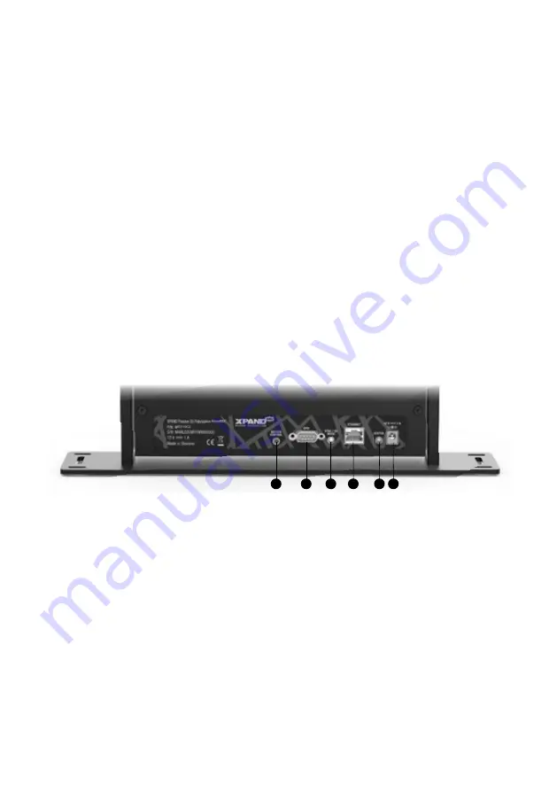
Connector Panel
(1) Motion Control - Typically used for controlling a motorized mount, if the modulator is attached to one. See section
Motion Control Output
for more information.
(2) GPIO - Connector for connecting the modulator to the projector. With use of special cables this connector can also be used for connecting
the projector’s or the digital cinema server’s GPIO ports to the modulator.
(3) SYNC / 3D MODE LED - Amber LED for indicating which mode the modulator is currently operating in.
(4) ETHERNET - RJ45 / Ethernet port used for connecting the modulator to the local network. Two square LEDs are integrated in the con-
nector, showing network activity of the unit.
(5) STATUS LED - Green LED for indicating current status of the modulator.
(6) DC12V 1A - Power in.
Inputs
»
GPIO Port: DSUB-9PIN-Male. See pinout diagram below for more information.
»
Ethernet Port: RJ45 / 8P8C Ethernet connector.
»
DC Power Jack: 6.2 mm
Φ
(Hole size), 1.6 mm
Φ
(Lead size). Mating connector: 5.5 mm
Φ
(OD), 2.1 mm
Φ
(Bore).
GPIO male 9-pin connector pinout
1
2
3
4
5
6
Summary of Contents for MS210C2
Page 19: ......
Page 20: ...to be used on dark background to be used on light background...


