background image

© XPAND, All Rights Reserved. 


www.xpandvision.com

Us ing the Confi guration Utility

The list below only gives a general description of confi guration utility’s features. For a more detailed and up to date explanation see the 
confi guration utility’s help fi le.

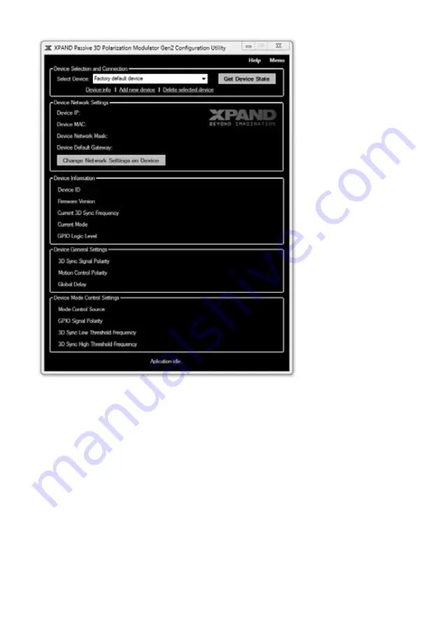
Device Selection and Connection

In a common setup a cinema theatre will have more than one cinema hall equipped with XPAND’s passive modulators and the operator 
will be able to access all of them from the same PC. To distinguish between all connected modulators a “known devices list” needs to be 
maintained. This section is used to manage such a list of known devices, connect to them and display and change the information about 
each one. The section features the following controls:


»

Select Device drop-down list:

 Used to select a device to connect to from a list of devices known to the utility. Devices must 

be added manually. See “Add new device” control description below.


»

Get Device State button:

 By pressing this button the utility attempts to connect to the currently selected device and retrieve its 

confi guration which it then displays.


»

Device info: 

Clicking on this control displays information about network parameters of the device currently selected in the 

“Select Device” drop-down list as known to the confi guration utility. A pop-up window which displays this information also 
allows modifying these parameters in the list. Note that if the actual settings of the unit are modifi ed from PC A, the ones stored 
by the confi guration utility on PC B will have to be modifi ed manually through the Device Info pup-up window.

Summary of Contents for MS210C2

Page 1: ...to be used on dark background to be used on light background XPAND Passive 3D Polarization Modulator Gen2 User Manual User Manual...

Page 2: ...ion 9 Installation 9 Motion Control Setup Wizard 10 Unit s Initial Network Settings Configuration 10 Recommended Projector Settings for XPAND Passive 3D Cinemas 12 Modulator Configuration Using the PC...

Page 3: ...he product Use of XPAND s Passive 3D Polarization Modulator Motorized Mount is strongly recommended Make sure that the modulator is never positioned in front of the projector when viewing 2D content A...

Page 4: ...s for connecting the unit to the projector 1 Ethernet Crossover Cable 1 User Manual WARNING The supplied Ethernet Crossover Cable should not be used as a regular network cable It is intended primarily...

Page 5: ...ING 1s ON 1s OFF The unit s mode control source is set to frame sync it is in 2D mode and scanning for a condition to transition into 3D mode This condition is a valid 3D synchronization signal on the...

Page 6: ...ion Modes of Operation The modulator operates in one of two modes 2D mode or 3D mode As their names suggest the 3D mode is intended for watching 3D content and 2D mode for viewing 2D content at which...

Page 7: ...mode is to monitor the 3D synchronization signal line coming from the projector for the presence of a valid synchronization signal This signal comes into the modulator through its GPIO connec tor If a...

Page 8: ...or to 3D mode modctrls n mode 3D Command Parameter Value Description mode 2D 3D Sets the currently active mode based on the input parameter value Note This command only takes effect if the Network Mod...

Page 9: ...r on the projector and to the 9 pin GPIO connector on the back of the modulator Two cables are supplied with the modulator Choose the correct one based on the available connectors on the projector 5 I...

Page 10: ...s lamp cannot reach the modulator by placing a non transparent light barrier between the projector and the modulator Alternatively the lamp on the projector can be turned off or if the projector allow...

Page 11: ...he IP is reserved network configuration is finished If however more modulators will be connected to the same network this unit s IP must be changed since each modulator requires a unique IP Proceed to...

Page 12: ...u PC network settings you may have changed in step 5b If an automatic connection attempt is not made by the utility initiate it manually by clicking the Get Device State button Once a successful conne...

Page 13: ...one The section features the following controls Select Device drop down list Used to select a device to connect to from a list of devices known to the utility Devices must be added manually See Add ne...

Page 14: ...Frequency Reports whether a synchronization signal is detected on the modulator s 3D sync GPIO input Validity of the signal and its frequency are reported Whether a signal is valid or not is determin...

Page 15: ...cy on the modulator enter a new value and press the Enter key to confirm the change The Menu Bar Most of the menu s items are self explanatory and intuitive However the following submenu items deserve...

Page 16: ...sure the filter is completely dry before inserting it back into the unit Remove the protective cover and plug the power jack back into the modulator If the filter shows sign of wear it should be repla...

Page 17: ...s or people with family members who have experienced such symptoms should consult their physician before viewing 3D media We recommend that Parents or Guardians observe their children while the childr...

Page 18: ...void the user s authority to operate it This device complies with part 15 of the FCC Rules Operation is subject to the following two conditions 1 This device may not cause harmful interference and 2 t...

Page 19: ......

Page 20: ...to be used on dark background to be used on light background...

Reviews: