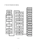
3
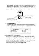
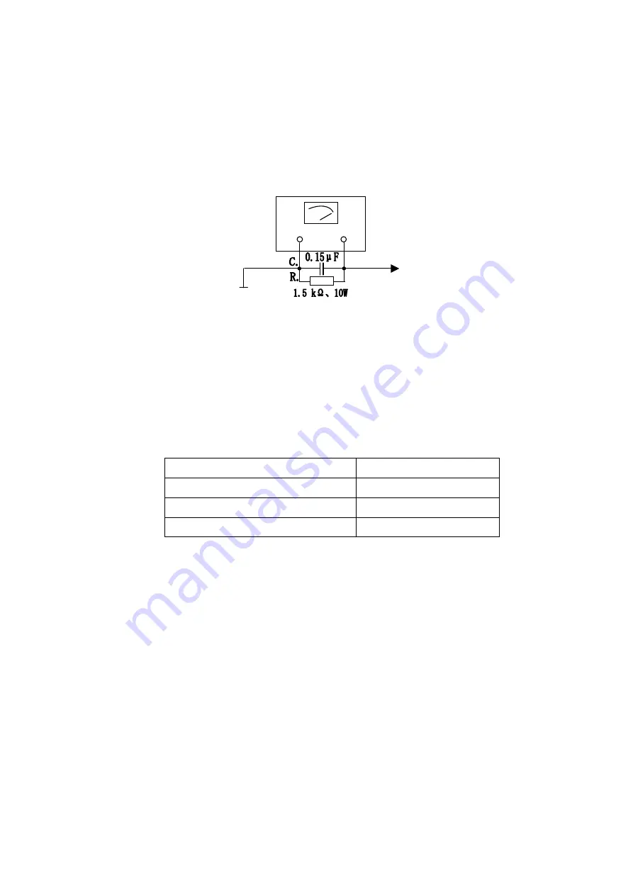
between the known good earthing connector (such as underground metal tube) and the
exposed metal parts out of the cabinet. Measure AC voltage across both terminals. Then
exchange the two pins of AC before re-measuring every exposed metal parts. The measured
value of voltage should not exceed 0.3V effective value, which corresponds to current.0.2mA
If the value exceeds this specified value, aligning must be made at once.
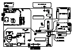
Figure 1
1.2. 7 DC voltage breakdown test
The following touchable parts must be subject to 1s anti voltage test before packing. The
voltage is applied between the plug pin of the power supply and the exposed metal parts for
the test and the volt value should be AC 3000V.
Parts designation:
Position:
Antenna terminal
Back cover
External cover screw
Back cover
AV interface
Back cover, sides
1.3 Points of attention for product safety
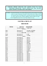
There are many electric and mechanical parts in this PCB that are related to safety. However,
they are often neglected from visual look. For changing the high voltage and high power parts,
very often it’s impossible to provide them with effective “X-ray radiation” protection. All these
exchange parts with safety characteristic are designated in the detail list. All the electronic
parts with such characteristics are indicated with shadow in the circuit diagram.
When changing these parts, please carefully check the detail list.
AC Volt Meter
Good Earth Connect Point
(Such as underground metal etc)
This detector is placed
respectively at every
exposed metal parts.


