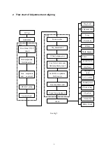
5
3. Alignment Equipment
3.1
DC Current Stabilizer Power Supply PAB18-1.8
3.2
Audio Frequency Voltage Meter
3.3
Oscillograph
3.4
High Voltage Meter
3.5
Digital Multi-meter
3.6
AC breakdown test meter
3.7
IFT Signal Gene
4. Alignment Instruction
4.1 Factory Alignment Methods
4.1.1
Push composed keys
→
--/---
→
to enter factory menu.
4.1.2
There are totally three pages of factory menu. Turn the page by pushing “MENU”, Move the
items by CH+/CH- key, Adjust the value by VOL+/VOL-. After adjustment, push “OK” for save.
4.1.3
The method to quit factory menu: Under the item VCT in SERVICE XOCECO-50 Hz, push
EXIT: OK
4.2 IF amplifier alignment
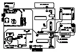
a) Connect the positive pole of TP5. C219 to DC 5v, TP2 or TP7 to positive pole DC 8v, TP6 to
earth, TP4 to multi-meter.
b) Connect 38.9M, PAL DK IF signal to TP1 through 1000p capacitor, adjust IFT L102 with zero
inductance screwdriver, to make the readout of multi-meter as 2.5V
±
0.1 V.
c) Connect 33.9M SECAM L IF signal to TP1 through 1000P capacitor, apply voltage 5v at TP1,
TP3, TP8, adjust RP101 with zero inductance screwdriver, to make the readout of
multi-meter as 2.5V
±
0.1 V.
d) After adjustment, connect the IF line disconnect point of tuner, seal L102 with wax, point glue
RP 101.
4.3 B+ confirmation
Determine the B+ voltage by DC meter, DC 200V ( C503 two poles) , the value should be 135
V
±
0.5.
4.4 AGC adjustment
4.4.1
Receive D-8 signal 60db, determine the voltage of positive testing pole of C114 with DC
voltage meter.
4.4.2
Adjust potentiometer RP107, to make the voltage readout of voltage meter to be 4.1 V
±
0.1V.
4.4.3
Input 100db from antenna, and the picture should not appear as asynchronized and
distorted. Input 35db-40db weak signal, and the color should not disappear, the picture
should be synchronized, and the sound is normal.


