8
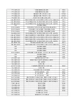
13. SECAM BGP
14. VIDEO OUTGAIN
Demodulation output range adjustment
15. OM DET
Over modified detecting on/off
16. S-SLICE DOWN
Sync detecting slice stage
17. AUTO SLICE DN
Auto detecting on/off
18. V SYNC DET
Vertical sync detecting
19. V-1 WINDOW
20. AFC1 GAIN UP
H AFC1gain
21. AFC2 GAIN DOWNN
H AFC2 gain
22.
ABCL
Brightness/contrast auto control
23.
ABCL
GAIN
Brightness/contrast auto control gain
24.
GAMMA
25. BLACK ST OFF
Black level delay on/off
26. BLACK ST ADJ
27. BLACK ST GAIN
28. VIF FREQ
VIF selecting
29.
VDL
ADJ
30.
UDL
ADJ
31. IC SELECTION
32. OP PAL-M/N
33. OP AV-SUSTEM
AV mode
34. AUDIO ATT
Volume output control
35.
MONITORING
36. EEPROM OPTION
EEPROM selecting
37. POW-ON SEARCH
Power-on search selecting
38. OSD H-POSITION
OSD horizontal position adjustment
39. EEP ADJ
EEPROM modifying
40. PIC-DYNAMIC
Dynamic scalar selecting
41. PIC-STANDARD
Standard scalar selecting
42. PIC-SOFT
Soft scalar selecting
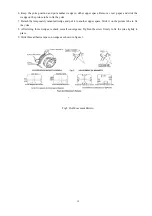
CONVERGENCE MAGNET ASSEMBLY POSITIONING
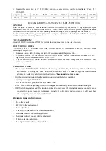
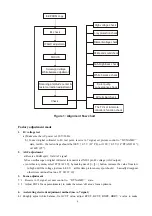
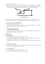
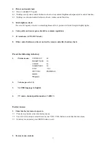
Convergence magnet assembly and rubber wedges need mechanical positioning. Refer to below figure 1.
COLOR PURITY ADJUSTMENT
NOTE: Before attempting any purity adjustment, the receiver should be operated for at least fifteen minutes.
1. Demagnetize the picture tube and cabinet using a degaussing coil.
2. Set the CONTRAST and BRIGHTNESS controls to the maximum.
3. Receive PM5515 monochromatic signal (such as G) to provide a green raster on the screen.
4. Loosen the clamp screw holding the yoke, and slide the yoke backward to provide vertical green belt
(zone) in the picture screen.
5. Remove the Rubber Wedges.
6. Rotate and spread the tabs of the purity magnet around the neck of the picture tube until the green
belt is in the center of the screen. At the same time, center the raster vertically by adjusting the
magnet.
7. Move the yoke slowly forward or backward until a uniform green screen is obtained. Tighten the
clamp screw of the yoke temporarily.
Summary of Contents for M2019
Page 1: ...COLOR TELEVISION M2019 TS2019 ...
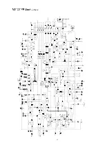
Page 14: ...12 ...
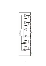
Page 17: ...15 1 2 3 4 5 6 7 8 9 10 11 12 Vcc GND AN7522N ...
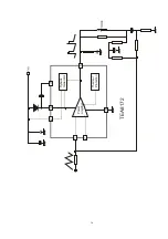
Page 18: ...16 Power Amplifier Thermal Protection Flyback Generator 1 7 4 5 3 6 2 TEA8172 ...
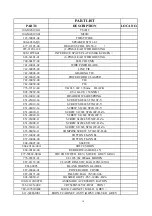
Page 39: ...18 ...

