5
4.4.2 Adjustment of white balance
Input HDMI signal and check the white balance at HDMI channel.
a) Enter “color temperature setting” menu, select “color temperature” of “NORMAL”.
b) Input 16-level gray signal of the mode 1024*768 @60HZ (TIMING:856, PATTERN:921).
c) Fix BLUE GAIN at 1000, adjust RED GAIN, BLUE GAIN to set the
color coordinates
of
fourteenth level to (X=285, Y=293).
d) Set the
color coordinates
of warm color temperature (WARM) to (X=300, Y=306) using the
same method.
e) Set the
color coordinates
of cool color temperature (COOL) to (X=270, Y=283) using the same
method.
f) Check if the color
coordinates
of the cool/warm color temperature at YPBPR (include
480P,720P), VIDEO(NTSC) and TV channels are within the scope of the correspond value
(permit ±8 error).
5 Functional Inspection
5.1 TV function
Connect RF-AIR terminal to the central signal source, Enter the channels menu
→
scan channels,
select input type “Antenna” to auto search and check if there is station skipping. Check if search
(
→
Find channel), the output of earphone and speakers, and the picture are normal.
5.2 AV/S-Video terminal
Connect AV/S-Video signal, check if they are normal.
5.3 YPBPR terminal
Input YUV signal (VG-848 signal generator), separate input the YUV format signal of table 1 and
check if the display and sound are normal.
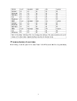
Table1 YUV signal format
NO
H-frequency (KHz)
V-frequency (Hz)
Signal
1 15.734
59.94
SDIV
480i
2 31.469
59.94
HDIV
480p
3 45
59.94
HDIV
720p
4
45 60 HDIV
720p
5
33.75 59.94 HDIV
1080i
6 33.75
60
HDIV
1080i
5.4 VGA terminal
Input VGA signal (VG-848 signal generator), separate input the VGA format signal of table1 and
table 2, check if the image and sound is normal. If the image is deflection of H-field, select Auto
Sync correction of the Screen Settings menu. If the image is slight disturb, adjust Phase correction
of the Screen Settings menu.
Summary of Contents for LC-32FC18
Page 1: ...LCD TELEVISION LC 32FC18 America ...
Page 16: ...14 Block diagram of TPA3008D2 ...
Page 17: ...15 Pin description ...
Page 29: ...CPU board ...
Page 30: ...CPU board ...
Page 31: ...CPU board ...
Page 32: ...CPU board ...
Page 33: ...CPU board ...
Page 34: ...CPU board ...
Page 35: ...CPU board ...
Page 36: ...CPU board ...
Page 37: ...CPU board ...
Page 38: ...CPU board ...
Page 39: ...AV trans connect board ...
Page 40: ...analog board ...
Page 41: ...32 power board 667 L32T18 20 ...
Page 43: ...APPENDIX Exploded view LC 32X18 ...
Page 45: ...603 L32FC18 14 Ver 1 1 ...


