


Introduction
2-1
Manual 0-4809
SECTION 2:
INTRODUCTION
2.01 Overview
Plasma is a gas which has been heated to an extremely
high temperature and ionized so that it becomes elec-
trically conductive. The plasma arc cutting process uses
this plasma to transfer an electrical arc to the work-
piece. The metal to be cut is melted by the heat of the
arc and then blown away.
2.02 General Specifications
System Descriptions
NXP35
Maximum Output
35 Amps
Input Voltage & Phase
230V,
Single Phase
Frequency
50/60Hz
Input Power
7.4 kVA
Current Input Fuse
20 Amps
No Load Voltage
330V
Load Voltage
94V
Output Current
15-35 Amps
Post Flow Time
10 Seconds
Operating Air Pressure
75 psi (5.2 bar)
Maximum Air Pressure
125 psi (8.6 bar)
Air Flow
400 scfh
6.6 scfm
(188.7 lpm)
System *Duty Cycle ratings
at Ambient Air Temperatures
of 40° C / 104° F.
35% @ 35Amps
System *Duty Cycle ratings
at Ambient Air Temperatures
of 40° C / 104° F.
60% @ 27Amps
System *Duty Cycle ratings
at Ambient Air Temperatures
of 40° C / 104° F.
100% @ 20Amps
Maximum Cutting Capacity
@ 35A
1/2" (12mm)
Dimension (W x D x H)
8.3"x20"x14.8"
(210 mm x 510
mm x 350 mm )
Net Weight
44 lbs.
(20kg )
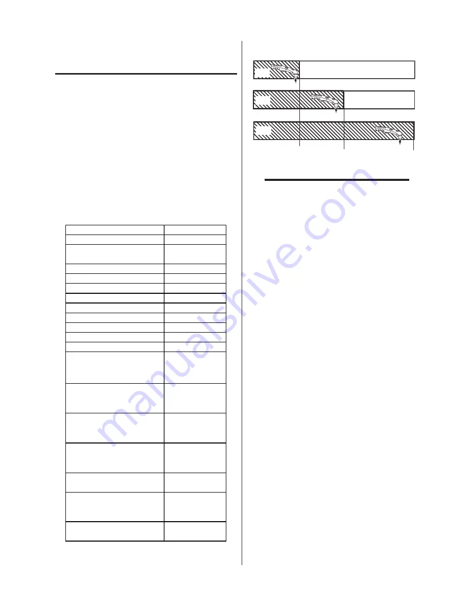
20A
27A
35A
35% (3.5 min)
60% (6 min)
100% (10 min)
OFF
OFF
CUT
CUT
CUT
Ar
t # A-0450
5
NOTE:
*Duty Cycle is the percentage of time the sys-
tem can be operated without overheating. Duty
cycle is reduced if primary input voltage (AC) is
low or the DC voltage is higher than shown in
previous chart.
2.03 Features
• PORTABLE - Weighing just 44 lbs., (20 kg) it is
easily moved from location to location.
• POWERFUL CUTTING PERFORMANCE
-
Maximum cutting capacity is 1/2” (12mm).
• CUTS MOST METALS - Useful for most metals
such as stainless steel, aluminum, mild steel, cop-
per and alloys.
• NO HIGH FREQUENCY - Starts without high-
frequency so it won’t interfere with controls or
computers.
• MORE TORCH, LESS MONEY - The SL60™
1Torch™ provides state of the art technology and
performance of more expensive torches.
Summary of Contents for NXP35
Page 2: ......


