xcore.ai Multichannel Audio Board 1v1 Hardware Manual
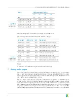
Mode
Shorting Jumper Position
J6
J9
J11
J13
I2S
2-3
2-3
2-3
2-3
TDM input on X_ADC_D0
1-2, 3-4
NO FIT
1-2
NO FIT
TDM input on X_ADC_D1
1-2
3-4
1-2
NO FIT
TDM input on X_ADC_D2
1-2
NO FIT
1-2, 3-4
NO FIT
TDM input on X_ADC_D3
1-2
NO FIT
1-2
3-4
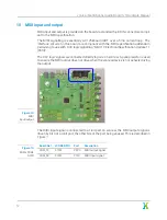
Figure 5:
Analog input
configuration
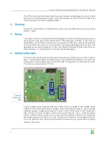
Pin 1 of each jumper is denoted by a triangle on the silkscreen.
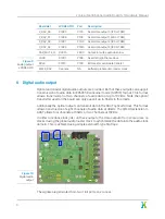
The ADC registers are accessed via the I2C bus - see §
Board Net
xCORE GPIO
Port
Description
X_ADC_D0
X1D24
P1I0
Serial data input 0 (I2S or TDM)
X_ADC_D1
X1D25
P1J0
Serial data input 1 (I2S or TDM)
X_ADC_D2
X1D34
P1K0
Serial data input 2 (I2S or TDM)
X_ADC_D3
X1D35
P1L0
Serial data input 3 (I2S or TDM)
ADC_GPIO
X0D33
P4E3
Multipurpose interrupt input
LRCK
X1D01
P1B0
Serial left/right frame clock
BCLK
X1D10
P1C0
Bit clock for serial data transfer
MCLK_ADC
See note
NA
Buffered global audio master clock
Figure 6:
Analog input
xCORE GPIO
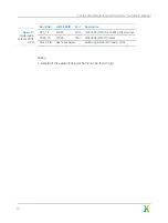
Notes:
·
Details of the audio clocking scheme can be found in §
7
Analog audio output
A total of eight single-ended analog output channels are provided via four 3.5mm stereo
jacks. The 8 analog outputs are generated by four 2 channel DACs (PCM5122). The DACs
are configured to accept digital audio over I2S or TDM. Configuration of the DACs is via
I2C. The full scale output level is 2.1Vrms.
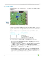
The four digital input channels ADC_D0 to ADC_D3 are mapped to the xCORE outputs
X_DAC_D0 to X_DAC_D3 through a header array as described in Figure
. Basic jumper
operation allows configuring the device to work in I2S or TDM mode. In I2S mode, each
wire carries 2 channels of audio so the 8 analog output channels map 1:1 to the four digital
outputs. In TDM mode, a single wire can carry up to 8 channels of data. This means the
four xCORE digital outputs can support up to 32 analog output channels. The jumpers
7


