


xcore.ai Multichannel Audio Board 1v1 Hardware Manual
13
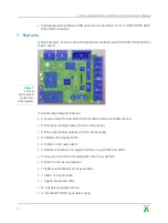
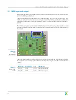
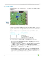
General purpose user interface
4 green LEDs and 3 buttons are provided for general purpose user interfacing.
The figure below shows the layout of the user interface subsection:
Figure 19:
User interface
components
The signal mapping of the user interface components is shown in Figure
Board Net
xCORE GPIO
Port
Description
LED_0
X0D28
P4F0
LED Output 0. Set high to light LED.
LED_1
X0D29
P4F1
LED Output 1. Set high to light LED.
LED_2
X0D30
P4F2
LED Output 2. Set high to light LED.
LED_3
X0D31
P4F3
LED Output 3. Set high to light LED.
BUT_0
X0D26
P4E0
Button input 0. High = not pressed.
BUT_1
X0D27
P4E1
Button input 1. High = not pressed.
BUT_2
X0D32
P4E2
Button input 2. High = not pressed.
Figure 20:
User interface
GPIO
14
I2C bus address map
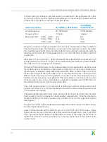
Due to a conflict in I2C slave addresses, two I2C buses are used on the board. These
buses are multiplexed onto the xcore.ai I2C bus using a PCA9540B 2-channel I2C-bus
multiplexer. This allows the I2C bus to be used (0 or 1) to be selected over I2C.
I2C slave address (7 bit)
Device
0x70
NXP PCA9540B 2-channel I2C-bus multiplexer
17