background image

USER MANUAL

 - OPTIMA-31 10K / 20K / 30K   


www.xmart-ups.com                                                                       

150615-OPT-31 10K/20K/30K (ENGLISH) - 4 


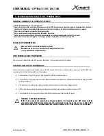
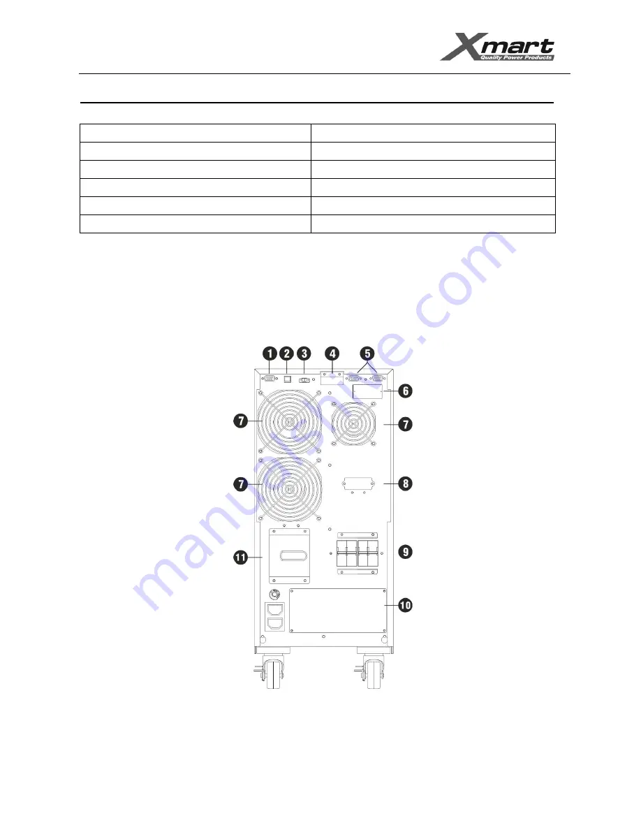
REAR PANEL   


1.- RS232 

7.- FAN for power stage / Ventilación Forzada etapa de potencia 

2.- USB 

8.- EXBATT connector / Conector Baterías Externas 

3.- EPO (Emergency Stop / Parada Emergencia) 

9.- AC Input Breaker / Breaker de Entrada AC 

4.- Share Current (for parallel UPS / para UPS paralelas) 

10.- Terminal block cover / Tapa Regleta Conexiones 

5.- Parallel Port (for parallel UPS / para UPS paralelas) 

11.- MBS (Bypass Switch / Interruptor Bypass) 

6.- Smart port / Puerto Inteligente 

18.- Ground Terminal Block Cover / Cubierta terminal de Tierra 


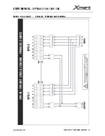
MODEL: (OPTIMA-31 10K) & (OPTIMA-31 

10K-NB) 


Summary of Contents for OPTIMA-31 10K

Page 1: ...manual Information cannot be copied or distributed totally or partially without written approval of XMART XMART can introduce modifications in their products or manuals without further notice XMART is...

Page 2: ...S INSTALLATION PARALLEL UPS TERMINAL BLOCK GENERAL COMMENTS UPS AC LINES CONNECTION PARALLEL CONTROL CABLES CONNECTION 6 START UP SINGLE UPS INSPECTION BEFORE START UP SINGLE UPS START UP PROCEDURE 7...

Page 3: ...duct is locked by screws Do not try to access inside the UPS unless you are a qualified technician UPS must be checked repaired and maintained by qualified personnel only CAUTION ELECTRIC SHOCK RISK C...

Page 4: ...er 25 C and optimal operational conditions This time can be dramatically reduced by high temperature and other adverse operation condition Batteries life expectancy may be also affected by other opera...

Page 5: ...dard UPS output It can provide 100 of the total capacity in watts of the UPS In battery mode this output is powered until UPS shutdowns because energy of the batteries has been drained Output 2 L2 N2...

Page 6: ...Externas 3 EPO Emergency Stop Parada Emergencia 9 AC Input Breaker Breaker de Entrada AC 4 Share Current for parallel UPS para UPS paralelas 10 Terminal block cover Tapa Regleta Conexiones 5 Parallel...

Page 7: ...3 EPO Emergency Stop Parada Emergencia 9 AC Input Breaker Breaker de Entrada AC 4 Share Current for parallel UPS para UPS paralelas 10 Terminal block cover Tapa Regleta Conexiones 5 Parallel Port for...

Page 8: ...3 EPO Emergency Stop Parada Emergencia 9 AC Input Breaker Breaker de Entrada AC 4 Share Current for parallel UPS para UPS paralelas 10 Terminal block cover Tapa Regleta Conexiones 5 Parallel Port for...

Page 9: ...hat case end user electrical contractor must be sure to comply with all related local electrical regulations and directives WARNING Power lines must be protected by protection devices against over cur...

Page 10: ...Installation site must be dry fresh free of dust fibers and any other objects conductors or not suspended in the air that could get into the UPS thru the ventilation system Fan Do not block UPS venti...

Page 11: ...ust be protected by magneto thermal protection devices against over current breakers with capacity and technology appropriate to effectively accomplish its function as indicated in this manual Moreove...

Page 12: ...bypass mode 208V Wiring min recommended size Phase 6 AWG 16 mm2 Neutral 6 AWG 16 mm2 Ground 6 AWG 16 mm2 Breaker 100Amps DC Curve C Wiring min recommended size 6 AWG 16mm2 30KVA 3PH 1PH Breaker 200 A...

Page 13: ...information given in this manual please follow terminal block information printed on UPS OPTIMA 31 10K 10K NB Output 1 L1 N1 This is the standard UPS output It can provide 100 of the total capacity in...

Page 14: ...2 This is a programmable output able to provide 100 of total UPS capacity This output can be configured to power off automatically in battery mode by reaching a programmable timer In this way non crit...

Page 15: ...USER MANUAL OPTIMA 31 10K 20K 30K www xmart ups com 150615 OPT 31 10K 20K 30K ENGLISH 13 OPTIMA 31 30K 30K NB...

Page 16: ...overs in UPS and EXBATT cabinets 3 Using appropriate cable supplied with the EXBATT connect UPS with EXBATT 1 In case of more than 1 EXBATT connect EXBATT 1 with EXBATT 2 and so on until last EXBATT 4...

Page 17: ...BLOCK PREPARATION Remove cover of terminal block at the UPS rear panel identified as 10 in rear panel section of this manual UPS INPUT AND OUTPUT CONNECTIONS Connect input and output ground wires to...

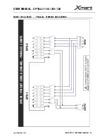
Page 18: ...USER MANUAL OPTIMA 31 10K 20K 30K www xmart ups com 150615 OPT 31 10K 20K 30K ENGLISH 16 MODEL 10K 10K NB PARALLEL TERMINAL BLOCK WIRING...

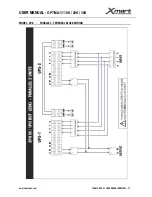
Page 19: ...USER MANUAL OPTIMA 31 10K 20K 30K www xmart ups com 150615 OPT 31 10K 20K 30K ENGLISH 17 MODEL 20K PARALLEL TERMINAL BLOCK WIRING...

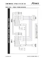
Page 20: ...USER MANUAL OPTIMA 31 10K 20K 30K www xmart ups com 150615 OPT 31 10K 20K 30K ENGLISH 18 MODEL 20K NB PARALLEL TERMINAL BLOCK WIRING...

Page 21: ...USER MANUAL OPTIMA 31 10K 20K 30K www xmart ups com 150615 OPT 31 10K 20K 30K ENGLISH 19 MODEL 30K 20K NB PARALLEL TERMINAL BLOCK WIRING...

Page 22: ...USER MANUAL OPTIMA 31 10K 20K 30K www xmart ups com 150615 OPT 31 10K 20K 30K ENGLISH 20 PARALLEL CONTROL CABLES...

Page 23: ...ower AC input at electrical panel board by setting input AC lines circuit Breaker to ON 3 Put Battery Bank breaker to ON Only for Ex Models If using external battery pack 4 Put AC INPUT Breaker to ON...

Page 24: ...this manual 7 Make sure total available capacity in Watts of all UPS to be connected in parallel is higher than load to be connected to UPS system It is recommendable total UPS power is at least 25 hi...

Page 25: ...eset according to warning and error section in this manual 8 When rear panel AC breaker is set to ON This UPS recognizes all other UPS previously powered ON in the parallel system and will get its own...

Page 26: ...ted in parallel 15 Check to confirm there are no error or alarm messages on LCDs At this moment all UPS are working in NORMAL Online mode and connected in parallel 16 It is time to power on equipments...

Page 27: ...to turn UPS OFF ESCAPE It Works as ESCAPE key when LCD is in configuration menu mode TEST UP BATTERY TEST When UPS is in normal mode by selecting TEST key UPS enters into battery test mode during 10...

Page 28: ...DICATOR LIGHTS There are 4 LED indication lights in front panel located below LCD These 4 LEDs describe UPS condition as follow MODE Bypass Line Battery Fault UPS is in Auto check mode during start up...

Page 29: ...s to battery mode elapsed time during battery mode is displayed in Hours Minutes Seconds 3 ERROR ALARM CODE In case of alarm or error 2 digits code is displayed in this section to describe the kind of...

Page 30: ...mal Online mode If an AC failure occurs under ECO mode the UPS s inverter starts working draining energy from batteries There is a transfer time of 4 ms typical This mode is configured and activated f...

Page 31: ...er On Description When UPS is powered on it will enter into this mode for a few seconds as initializing the CPU and system LCD display No output mode Description When bypass voltage frequency is out o...

Page 32: ...within acceptable range UPS will provide pure and stable AC power to output The UPS will also charge the battery at AC mode LCD display Only if UPS is connected to parallel system ECO mode Description...

Page 33: ...requency 50 Hz or 60 Hz At this mode the UPS will have no bypass output but still charge battery LCD display Only if UPS is connected to parallel system Battery mode Description When the input voltage...

Page 34: ...ypass mode Alarm beeps every two minutes LCD display Only if UPS is connected to parallel system Battery Test Description When UPS is in AC mode or CVCF mode press Test key for more than 0 5s Then the...

Page 35: ...t the warning situation In the warning screen the icon will be flashing and it can show up to 3 error codes and each code indicates one error You can find the code meaning in the warning code table LC...

Page 36: ...electrical isolation 6 There must be enough physical room to allow comfortable access to all UPS of the system Note if any of the above requirements cannot be complied below procedure must not be perf...

Page 37: ...ions Configuration function is identify in the upper side of the display in parameter 1 Parameters 2 3 indicates available options or values for each function Configuration menu texts TEXT DESCRIPTION...

Page 38: ...e range for bypass 04 Frequency range for bypass 05 ECO mode enable disable 06 Voltage range for ECO mode 07 Frequency range for ECO mode 08 Bypass mode setting 09 Maximum battery discharge time setti...

Page 39: ...ty frequency If it is from 46Hz to 54Hz the output frequency will be 50 0Hz If it is from 56Hz to 64Hz the output frequency will be 60 0Hz ATO is default setting Parameter 3 Frequency mode Setting out...

Page 40: ...64 0Hz 05 ECO mode enable disable Interface Setting Parameter 3 Enable or disable ECO function You may choose following two options DIS disable ECO function ENA enable ECO function If ECO function is...

Page 41: ...own to protect battery if the discharge time arrives before the battery is under voltage The default value is 990 min DIS Disable battery discharge protection and backup time will depend on battery ca...

Page 42: ...tion is Firstly enter this menu and press the Enter key to make the CHE flash Secondly press the Enter key again to activate the neutral detection check If neutral is detected the alarm will be muted...

Page 43: ...ally used for parallel operation 17 Phase auto adapt enable disable Interface Setting Parameter 2 it always shows PH A as PHASE AUTO ADAPT Parameter 3 it allows enable or disable this function DIS Dis...

Page 44: ...BEEP ALARM 01 Bus failure Continuous Beep 02 Hi BUS Voltage 03 Low BUS Voltage 04 Bus Unbalanced 06 Converter Over Current 11 Inverter soft start failure 12 Inverter HI voltage 13 Inverter LOW voltag...

Page 45: ...In parallel systems bypass situation different 33 Locked in bypass after overload 3 times in 30min 34 Converter current unbalance 35 Battery fuse broken 36 Inverter inter current unbalance 3A Cover of...

Page 46: ...le Beeping every second Fan failure Over temperature Beeping every second Charger failure Beeping every second I P fuse broken Beeping every second Overload 3 times in 30min Beeping every second ALARM...

Page 47: ...2 beeps per second UPS overloaded Disconnect devices from UPS outlets until solving overload Intermittent 2 beeps per second By Pass activated UPS overloaded UPS has changed to BYPASS mode to avoid in...

Page 48: ...ery Mode Modo Bater a EFFICIENCY EFICIENCIA Eco Mode 96 100 load AC Mode Modo AC 90 100 load Battery Mode Modo Bater a 89 100 load BATTERIES BATERIAS Internal Battery Pack Bater as Internas 12V 9AH 1...

Page 49: ...ctable by LCD El Voltaje de salida es configurable entre 4 alternativas seleccionables en el LCD N2 Backup time for programable outlets is configurable in minutes by LCD to offer longer time to critic...

Page 50: ...it is out of warranty because any of the reasons described in this warranty 6 If product is out of warranty a reparation proposal will be sent to the user for his approval If proposal is not accepted...

Reviews: