


10
OVEN THEORY OF OPERATION
When the main power on the Large User Interface (LUI) is turned on:
1. The Oven Fan Motor (Ml) located in the Back Wall will run.
2. The Fan (M3) located on the Control Panel will run.
3. The LUI will display actual temperature until set point is reached.
4. The LUI will display belt time.
5. The conveyor belt will move.
The first part of the Theory of Operation explains how electrical power is delivered to the
oven and initial sequences when the main power on the LUI is turned on. The remainder of the
Theory of Operation section explains the function of components in alphabetical order. These
components are also listed on the schematic.
• Line voltage for Standard Ovens is assumed to be 208/240 V AC, 3<1>, 60 Hz.
• Line voltage for World Ovens is assumed to be 380 VAC, 3<1>, 50 Hz.
Power originates at the electrical connection on the wall. Line voltage is then carried into
the oven through the power cord to the Power Block (PB). 3 wires come off the bower block. One
wire goes to the Circuit Breaker (CB) and then continues on to the Power Supply (PS). The other
leg acts as a neutral for the PS and The Main Motor (Ml). After the PS, 24 VDC is delivered to the
Terminal Strip (TS2). From the other side of the TS2, power is then supplied to the Oven Control
(OMC).
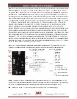
When the main power button is turned on, line voltage will be carried through the Main
OMC the TS2 #6L after a 30 second delay.
• The OMC sends power to the Oven Fan Motor Relay (RI) or the Oven Fan Motor Frequency
Drive (VFD World and Australia Only). Which then delivers power to the Oven Fan Motor (Ml).
Once the Main Motor Centrifugal Switch (S2) closes it provides power to the coil of the Contac
tors (Cl and C2), which opens the contactor sending power to the SSRs (SSRI-4) and Heating
Elements (Hl-H6). The SSRs are elements controlled by the OMC.
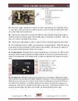
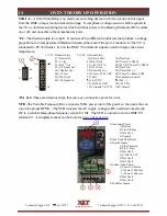
Cl
&
C2
- A contactor is an electrically controlled switch used for switching a power circuit. A
contactor is controlled by a control circuit that has a much lower power level than the switched
circuit. They consist of a small coil and a set of three SPST contacts. When the LUI is turned on
and the S2 is closed, 24 VDC voltage is applied to the coil, which closes the contacts. Then power
is allowed to flow to the SSR's. If the temperature at S3 exceeds 600
°
F, or if Ml does not rotate,
then voltage is interrupted to the coil, and will open the contactors.
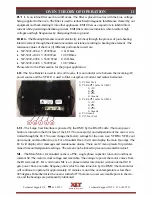
CAP
- The Capacitor is physically mounted inside the Control Box but wired to the externally
mounted Ml. The Ml is a Permanent Split Capacitor (PSC) motor. PSC means a capacitor motor
in which the starting capacitor and the auxiliary winding remain in the circuit for both starting and
running. The CAP is a 30.0 uF +/- 6% 370VAC/B 50/60 Hz.
CB
- Circuit Breakers are used to protect electrical components. The current value is printed on the
front of all breakers. If a CB is tripped, eliminate the cause and press the front to reset.
Technical Support US: 888-443-2751
S
i
mple
.
Smart.
Technical Support INTL: 316-943-2751


