12
ML40x Getting Started Tutorial
UG083 (v5.0) June 30, 2006
Board Setup
R
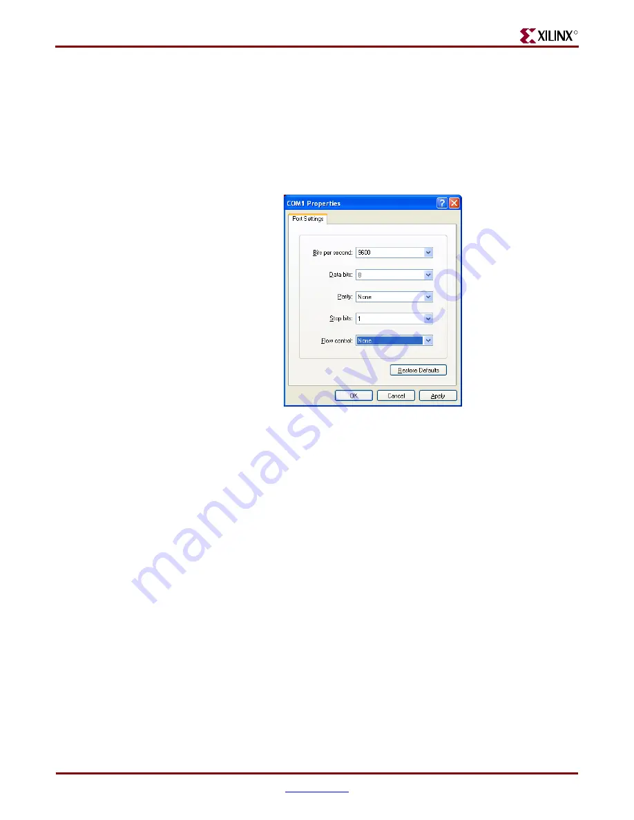
Use the pull-down menu to set the COM1 properties (see
) to the following:
♦
Bits per second = 9600
♦
Data bits = 8
♦
Parity = None
♦
Stop bits = 1
♦
Flow control = None
♦
Click
OK
→
OK
to accept settings
7.
Connect the VGA monitor to the board, if available.
8.
Turn on the ML40
x
board’s main power switch, and press the System ACE
RST
button. After the FPGA has been programmed, the LEDs in the lower left corner
should be:
♦
Bus Error 1 and 2 = off
♦
FPGA INIT = green
♦
FPGA DONE = green
♦
System ACE “Err” = off
♦
System ACE “Stat” = green
Note:
When the CF card is ejected or not installed, the System ACE “Err” LED blinks.
9.
Extract the associated training lab files to your local PC.
Unzip the training lab files to a working directory, name the directory, and make note
of the directory’s name. This directory with the extracted files is referred to as
<
LAB_DIR
> in this tutorial.
Figure 3:
COM1 Properties Setup
UG083_03_110204


