background image

6

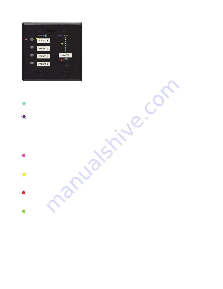
Power status LED

When the device is Powered On, this indicator will light blue.

Network LED

When the device has an Ethernet cable connected, the Network status 
LED will light orange once the processor initializes. If there is no Ethernet 
cable attached, this light will remain off. 
Note: When the Network status LED is on, it does not indicate that you 
have established a Network connection - only that an Ethernet cable is 
connected to the processor. Proper Network connection is displayed in 
Xilica Designer’s Network view. For more detail please refer to ‘Network 
view’ on Page 12.

On/off push button

Program processor on/off control functions into any Mini devices on/off 
push button using the Xilica Designer software. 

Label slot

Place supplied or unique label in label slot and cover with included 
protective plastic cover.

Level control

Program processor level control function into anyy Mini devices using the 
Xilica Designer software.

Level indicator LED

NeuPanel:Hardware device

Summary of Contents for NeuPanel Mini K1

Page 1: ...1 NEUPANEL MINI User Manual...

Page 2: ...ding prong The wide blade or the third prongs are provided for your safety If the provided plug does not fit into your outlet consult an electrician for replacement of the obsolete outlet 10 PROTECT T...

Page 3: ...ork 8 b To mains power 9 Install Xilica Designer software a Windows installation 10 b Mac installation 11 Xilica Designer s Network View a Device network status 12 b Connection troubleshoot 13 14 c Ma...

Page 4: ...graphics card 4 GB of RAM External power supply is included but it is recommended to use a PoE router switch Ethernet cable Cat5 6 Getting Help Additional Help Files and video tutorials are available...

Page 5: ...Mini K4 Control any four value changes including gains threshold frequency etc NeuPanel Mini S4 Control any four buttons in the system design including Preset selection NeuPanel Mini S8 Control any ei...

Page 6: ...nly that an Ethernet cable is connected to the processor Proper Network connection is displayed in Xilica Designer s Network view For more detail please refer to Network view on Page 12 On off push bu...

Page 7: ...ernet Power supply connector Power the device using the included external power supply If you are sending Power over Ethernet PoE the external power supply is not needed IP Reset button Reset the IP A...

Page 8: ...ering on the Hardware This will allow for proper handling of IP address distribution to the Hardware The IP address assignment is automatic if connected to a DHCP enabled network A DHCP enabled router...

Page 9: ...tored IP addresses or revert to its default IP address and thus refuse to connect We recommend performing an IP Reset Page 13 2 Multiple mini controls Non DHCP For multiple mini controls connected to...

Page 10: ...k Install to continue 4 Allow the program to complete the installation process This may take a several minutes 5 When complete Windows will ask for permission to allow firewall access The suggested se...

Page 11: ...download the latest version of the Xilica Designer software from the Xilica website www xilica com 2 Double click on the XilicaDesigner mpkg file saved on your computer 3 OSX will display an installat...

Page 12: ...ays three colors red yellow and green Circled in Red Network Connection Indicators Green The device is Connected and operational Yellow The device is Connected and online but not operational Hovering...

Page 13: ...be green indicating that the processor is connected online and operational Note If you are Not connecting via Wi Fi turn off your device s Wi Fi so the device can connect to the desired network If th...

Page 14: ...irmware Upgrade The pop up message shown will print out an error code Retry the Firmware Upgrade again Device can communicate to Xilica Designer with UDP but cannot communicate with TCP 1 Right click...

Page 15: ...the Network tab select Change Network Configuration to disable DHCP and to insert IP addresses manually It also provides two built in test procedures device security and device information along with...

Page 16: ...IPv4 then Properties to access the manual IP settings 5 Set up your computer s IP address to be 192 168 1 X where X can be any value from 0 255 but unique from other manually assigned device IP addre...

Page 17: ...ngs for your computers static address IP address 192 168 1 X X is any value from 0 255 but unique from other device IP addresses Subnet mask 255 255 255 0 Router 192 168 1 1 7 Click Ok and Apply to ap...

Page 18: ...o view the current software version click on the About tab at the top of the software This window will display your current software version Matching the Firmware To assist you in determining which fi...

Page 19: ...op left of each device 2 Save any design files from the device onto your computer All programmed data on the device will be erased during the upgrade process To save navigate to the File tab at the to...

Page 20: ...rade can result in a complete corruption of the processor If this happens please follow the Xilica Designer Firmware Upgrade guide Note If more than one unit needs a firmware upgrade you can save time...

Page 21: ...series DSP is rather different from Solaro series DSP therefore the two DSPs cannot be used in the same project file For more information please visit the Xilica Designer section in the Xilica website...

Page 22: ...project in offline mode no devices connected and later go online when all devices are connected 2 Double click the Mini module to open the device The NeuPanel Mini S4K1 on off buttons and level contro...

Page 23: ...To program the Mini S4K1 level control fader Double click the DSP module to open it Double click the parameter module that you d like to program Select the desired fader by holding Cmd Click Mac or Ct...

Page 24: ...f buttons Select the desired buttons from the DSP module by holding Cmd Click Mac or Ctrl Click PC Click and drag the selected buttons onto a Mini S4K1 control button Programmed buttons will turn gree...

Page 25: ...esigner User manual Simply click and drag the desired preset onto an available button on the wall control To change a control preset to another saved preset Select the button control that you would li...

Page 26: ...the desired control that you would like to rename 3 In the Object Properties menu rename the control in the Label Text Remove a programmed control button 1 Select the desired button fader on the wall...

Page 27: ...ject by clicking the File tab at the top left of the software and Save Or save your project using the save icon at the top right of the software 3 Once done each mapped module in the work area is a so...

Page 28: ...work area is now a solid color This indicates that you are in online mode Also the previous Load Design to Device s button has now changed Switch to Design Mode Switching from Online mode to Design mo...

Page 29: ...support xilica com and we ll connect you with a solutions engineer Alterna tively if you d like to speak to someone you can call the following numbers for immediate assistance North America Rest of wo...

Reviews: