www.arrl.org
QST
February 2023 41
nector, the coax from the transceiver to the SO-239
TRX
, and the power amplifier (PA) key cables from the
COMM
3.5-millimeter port to your transceiver. The PA
key interface is not necessarily compatible with all
transceivers. A ground enables the amplifier. How-
ever, if 3.2 V dc or more is applied to the XPA125B
PTT port, the internal processor will be permanently
damaged. The optional CE-19 interface provides
ALC, PTT, and band-changing information for the
Xiegu X5105 and G90 transceivers, and the correct
PTT interface for non-Xiegu transceivers. The Xiegu
X108 and X6100 transceivers interface directly with
the XPA125B without requiring the CE-19. If you are
using Xiegu transceivers, set the input power to 5 W,
as the ALC interface will adjust the driving power as
required. For non-Xiegu trans-
ceivers, the input power should be
initially set to 1 W. Finally, connect
the 13.8 V dc into the
DC IN
port,
and turn on the amplifier by press-
ing the power button for 2 sec-
onds (see Figure 1 for the rear
panel connection ports).
Performance
Measurements
Because the XPA125B will typi-
cally be used with 5 W QRP trans-
ceivers, I tested it up to a maxi-
mum of 5 W drive, as the specifi-
cations note that this is the typical
drive level needed for full power.
Table 2 details the measured
amplifier input versus output. The
XPA125B display power readings
are compared to a NIST-traceable
Array Solutions PowerMaster
(input), and Mini-Circuits PWR-
6GHS+ sensor and calibrated
attenuators (output).
The first thing I noticed was that
there was about a 0.5 to 0.6 V dc
voltage drop through the dc con-
nector on the XPA125B at the
higher current levels. There was
another 0.3 V drop along the 3-foot
dc power cable supplied with the
unit. The XPA125B power con-
nector is a six-pin Molex, but only
two tin-plated pins are used for
power. Also, the power cable
appears to be about 16 gauge, but
14- or 12-gauge wire would be
Figure 2
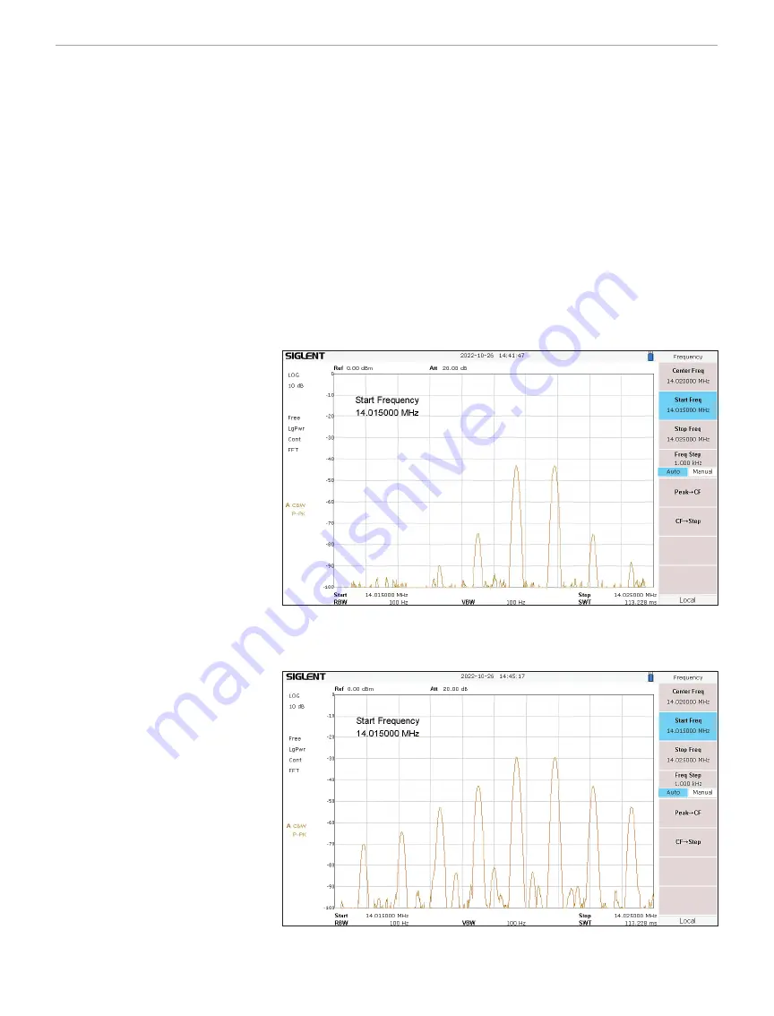
— The Xiegu XPA125B two-tone test with the Elecraft KX3 set at 5 W output.
Figure 3
— The Xiegu XPA125B resultant two-tone output.
more appropriate. To keep the voltage at 13.8 V dc on
the XPA125B display, I had to set my power supply to
14.6 V dc. This resulted in 100 W output on 20 meters.
Setting my power supply to 13.8 V dc resulted in the
maximum output on 20 meters dropping to 94 W. Also,
the XPA125B internal wattmeter appears centered in
accuracy on 20 meters. It reads low below 20 meters,
and high above 20 meters. So, while the internal watt-
meter appears to show that you are close to the typical
80 W specification on 6 meters, the actual power is
62 W with 5 W drive. Also, the input power monitor
reading is significantly in error. Finally, I found that the
input and output SWR and power readings do not
work unless the amplifier is on-line and being keyed.
Of course, when this is the case, the input SWR


