


microDXP Technical Reference Manual
Version 3.15
October 7, 2019
56
After an x-ray has been detected, the step height is measured at the slow filter output.
Although its excellent noise reduction also allows detection of the very lowest energy x-
rays, its slow response precludes an accurate determination of pulse pileup. For this reason
the slow threshold should be disabled in almost all cases.
4.6 Peak Capture Methods
As noted above, we wish to capture a value of V
x
for each x-ray detected and use these
values to construct a spectrum. This process is also significantly different between digital
and analog systems. In the analog system the peak value must be “captured” into an analog
storage device, usually a capacitor, and “held” until it is digitized. Then the digital value is
used to update a memory location to build the desired spectrum. During this analog to
digital conversion process the system is dead to other events, which can severely reduce
system throughput. Even single channel analyzer systems introduce significant deadtime
at this stage since they must wait some period (typically a few microseconds) to determine
whether or not the window condition is satisfied.
Digital systems are much more efficient in this regard, since the values output by the filter
are already digital values. All that is required is to capture the peak value – it is immediately
ready to be added to the spectrum. If the addition process can be done in less than one
peaking time, which is usually trivial digitally, then no system deadtime is produced by the
capture and store operation. This is a significant source of the enhanced throughput found
in digital systems.
Once an active threshold is exceeded, the microDXP employs one of two methods to
capture the slow energy filter output such that the best measure of V
x
results:
1.
The slow filter output is monitored over a finite interval of time in the region of its
maximum, and the maximum value within that interval is captured. This method
is referred to as
Peak Sensing
.
2.
The slow filter is sampled at a fixed time interval after the pulse is detected by the
fast filter. This method is referred to as
Peak Sampling
.
Before getting into the details of the two methods in §4.6.2, it’s important to understand
the impact of the slow filter gap length.
4.6.1 The Slow Filter Gap Length
The slow filter gap time, defined by SLOWGAP, is visible as the ‘flat-top’ region of the
energy filter output trapezoid. To properly sample the pulse amplitude, the gap time should
be set conservatively, to a value greater than the preamplifier 0-100% rise time.
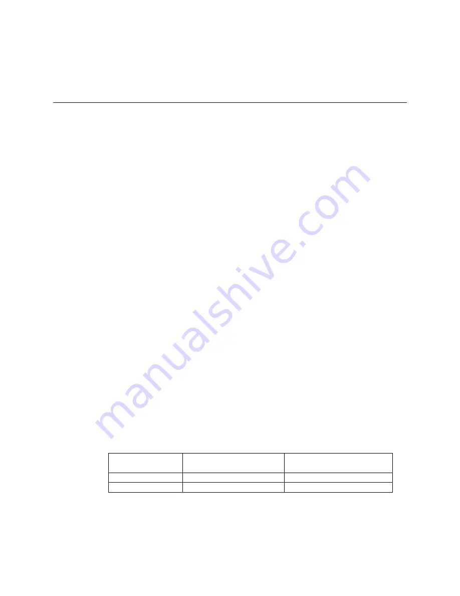
SLOWGAP is constrained by the relationship between the slow and intermediate filters:
the SLOWGAP increment is either 2x or 4x the clock period, as shown in the table below.
PARSETs
SLOWGAP increment
(w/ 40MHz clock)
SLOWGAP increment
(w/ 80MHz clock)
0 to 7
50 ns
25 ns
8 to 23
100 ns
50 ns
Table 4-1: The SLOWGAP units are constrained to 2x or 4x the clock period, depending on the
PARSET, i.e.
Peaking Time
.
Note:
at very short peaking times and at high count rates, it may be beneficial to set the gap
time shorter than the preamplifier rise time in order to increase throughput.


