


Phaser 6180 Color Laser Printer Service Manual
4-7
General Troubleshooting
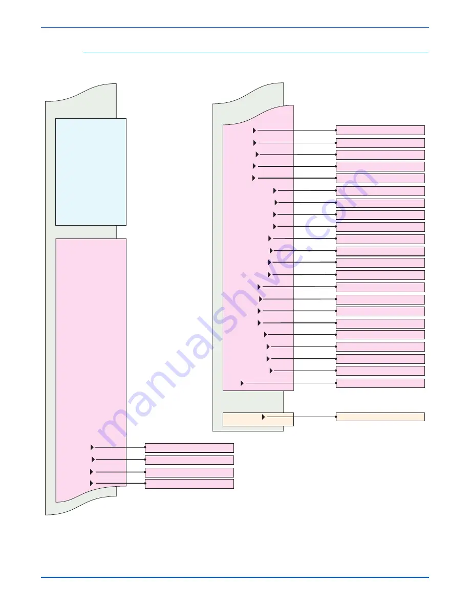
Menu Map - Page 2
Test Print
Parameter
Parameter (Cont.)
No Image IOT
TestPat600 IOT
Grid 2 ESS
Cyan 20% ESS
Magenta 20% ESS
Yellow 20% ESS
Black 20% ESS
CMY 20% ESS
Gradation ESS
Exit Mode
Complete Exit
Slow Scan KtoP
Slow Scan 600M
Slow Scan 600Y
Slow Scan 600C
Slow Scan 1200M
Slow Scan 1200Y
Slow Scan 1200C
Fast Scan KtoM
Fast Scan KtoY
Fast Scan KtoC
Fast Scan MPT
Fast Scan Tray 2
Fast Scan Tray 3
Fast Scan Duplex
Fast Scan 2 KtoM
Fast Scan 2 KtoY
Fast Scan 2 KtoC
Life Y Toner
Life M Toner
Life C Toner
Life K Toner
Life DTB1
Life Fuser
Life Printer
Life DTB2
Life DTB3
Life YWasteToner
Life MWasteToner
Life CWasteToner
Life KWasteToner
Life Developer Y
Life Developer M
Life Developer C
Life Developer K
Life Y Drum
Life M Drum
Life C Drum
Life K Drum
Life MPT Feed
Life Tray2 Feed
Life Tray3 Feed
Life Duplex Feed
Life Y Toner: 0
Life YWaste Toner: 0
Life MWaste Toner: 0
Life CWaste Toner: 0
Life KWaste Toner: 0
Life Developer Y: 0
Life Developer M: 0
Life Developer C: 0
Life Developer K: 0
Life Y Drum: 0
Life M Drum: 0
Life C Drum: 0
Life K Drum: 0
Life MPT Feed: 0
Life Tray 2 Feed: 0
Life Tray 3 Feed: 0
Life Duplex Feed: 0
Ready*
Exit?
Life M Toner: 0
Life C Toner: 0
Life K Toner: 0
Life DTB1: 0
Life Fuser: 0
Life Printer: 0
Life DTB2: 0
Life DTB3: 0
s6180-455
*Prints current parameters
Summary of Contents for Phaser 6180
Page 1: ...Service Manual Phaser 6180 701P45793 Color Laser Printer ...
Page 2: ......
Page 14: ...xii Phaser 6180 Color Laser Printer Service Manual ...
Page 24: ...xxii Phaser 6180 Color Laser Printer Service Manual Contents ...
Page 234: ...3 108 Phaser 6180 Color Laser Printer Service Manual Error Messages and Codes ...
Page 318: ...4 84 Phaser 6180 Color Laser Printer Service Manual General Troubleshooting ...
Page 376: ...5 58 Phaser 6180 Color Laser Printer Service Manual Print Quality Troubleshooting ...
Page 386: ...6 10 Phaser 6180 Color Laser Printer Service Manual Adjustments and Calibrations ...
Page 500: ...110 Phaser 6180 Color Laser Printer Service Manual Service Parts Disassembly ...
Page 594: ...10 54 Phaser 6180 Color Laser Printer Service Manual Plug Jack and Wiring Diagrams ...
Page 606: ...A 12 Phaser 6180 Color Laser Printer Service Manual Reference ...
Page 615: ......
Page 616: ...701P45793 ...


