Xerox Dove, Technical Reference Manual
The VIZULO Dove is a sleek and modern lighting fixture designed to enhance any space. Achieve a flawless installation with our comprehensive Mounting Instruction manual, available for free download from our website. This handy manual ensures a hassle-free setup, allowing you to fully enjoy the elegance of the VIZULO Dove.
Share
Download


Reviews:
No comments
Related manuals for Dove

G-RAID Studio
Brand: G-Technology Pages: 51

VANGARD
Brand: Asgard Pages: 3

175972
Brand: SanDisk Pages: 2

QDFLD25-***MUH1I Series
Brand: Quantum Pages: 23

PR97060
Brand: Dancover Pages: 66

SAS 760J
Brand: JetStor Pages: 71

ThunderBox 400
Brand: Thunderbolt Pages: 37

RP-SM16GFE1K
Brand: Panasonic Pages: 18

CS100
Brand: Canon Pages: 76
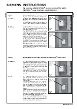
SENSORPROM
Brand: Siemens Pages: 2

SISTORE AX
Brand: Siemens Pages: 40
Gigaset USB Stick 108
Brand: Siemens Pages: 58

SIMODRIVE 611-D
Brand: Siemens Pages: 1154

SO MOBILE OTB HELLO KITTY
Brand: DANE-ELEC Pages: 2

CWC38
Brand: Clarke Pages: 8

PegasusPro R16
Brand: Promise Technology Pages: 80

SSG-2028R-DN2R20L
Brand: Supermicro Pages: 82

6048R-E1CR60L
Brand: Supermicro Pages: 82


