


3
Remote Control Switchers
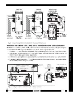
INSTALLATION – COMMON IR BUS SYSTEMS
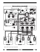
Fig. 3 illustrates a typical installation using three RGC11's along with other Xantech products in a 4-room
common IR bus system. The principles shown should be used as a guide when planning your own specific
installations. It is configured as follows:
1. For simplicity, only three RGC11's are shown. A practical limit would be six RGC11's "daisy-chained"
using the "LOOP THROUG H" jacks as shown. This places a load of 7.5k Ohms (45k Ohms
÷
6) on
the REC OUT jacks (or other driving source) of the main room receiver, etc. Use a Xantech AV-61
Distribution Amplifier when driving more than six. Each output of an AV-61 will drive as many as six
RGC11's.
NOTE: The REC OUT jacks on the receiver, amp, etc., are used since they provide a fixed output
independent of the main volume control.
2. A
common IR bus connects the 780-80 "J" Box IR Receiver,the 480-00 "Dinky Link" IR Receiver, and
two Smart Pad
3
keypads to each of the three RGC11's. In addition, it connects to a 789-44 Connecting
Block for control of the source components.
3. Since a common IR bus is used, each of the RGC11's and its connected MIRV1 (where used) must
use a different IR Code Group number, so that the volume level in each room can be adjusted
independent of the others. To make code group changes, refer to the RC68+ (or RC68) Programmer
Instructions.
NOTE:
When shipped from the factory, the RGC11 is set to code group number 30. If you use
group 30 or change to a different number, be sure to always set the RC68+ to the same number.
4. When a code group is chosen, "teach" volume commands from the RC68+ Programmer (see Fig. 2)
into learning remote controls (and the keypad), dedicated to each room. You may use the Xantech
URC-1 or URC-2 learning remote controllers for this purpose.
NOTE:
With a Common IR Bus system, you cannot carry the same remote control from room-
to-room. You must use a dedicated remote for each room into which you have "taught" the
specific RC68+ code group that operates the specific RGC11 that controls the volume for that
room!
If you wish to carry remotes that have the same codes from room-to-room, use a Dedicated IR Bus
System as shown in Fig. 4.
5. A 490-30 "Micro Link" IR Receiver plugs into the 789-44 for local control of the source equipment (e.g.
equipment behind closed doors, etc.).
6. A "STATUS" system is included. This permits the power "ON/OFF" status of the A/V receiver or
amplifier system to be visible in each of the remote rooms. It also permits the power management
capability of the SmartPad3 to operate.
7. The "STATUS" indicator LEDs on the 780-80 "J" Box IR Receiver and the two SmartPad
3
's, are
powered by a 786-00 Power Supply plugged into a "SWITCHED" AC outlet on the A/V receiver or
amplifier system. When the switched outlet is "ON", +12 Volts from the 781C-00 passes through one
of the 4 bus-conductors (STATUS line) to the LED indicators.
NOTE: A resistor can be placed in series with the STATUS terminal at each IR receiver (IR receivers
only, if so equipped) for adjustment of the brightness of the Status LED. See the specific installation
instructions for the IR receiver for details.
NOTE:
When connecting system devices, be sure to carefully match up the terminals according to
their markings as follows:
IR IN or OUT (IR Signal), ST (Status), G (GND and V (+12 VDC).
Power Supply Considerations
Use one 15V AC power supply (included) for each RGC11. Add up the individual currents for each of the
other IR components in the system and choose the power supply accordingly. For instance, use the 781RG
for current demands up to 200 mA. For higher demands up to 1 A, use the 782-00 power supply.
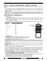
RGC11


